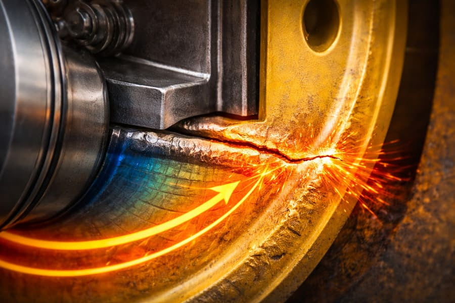
You see a crack right next to the weld1 on a failed OTR wheel2. Your first thought is a bad weld1, a manufacturing defect. But what if the weld1 was perfect?
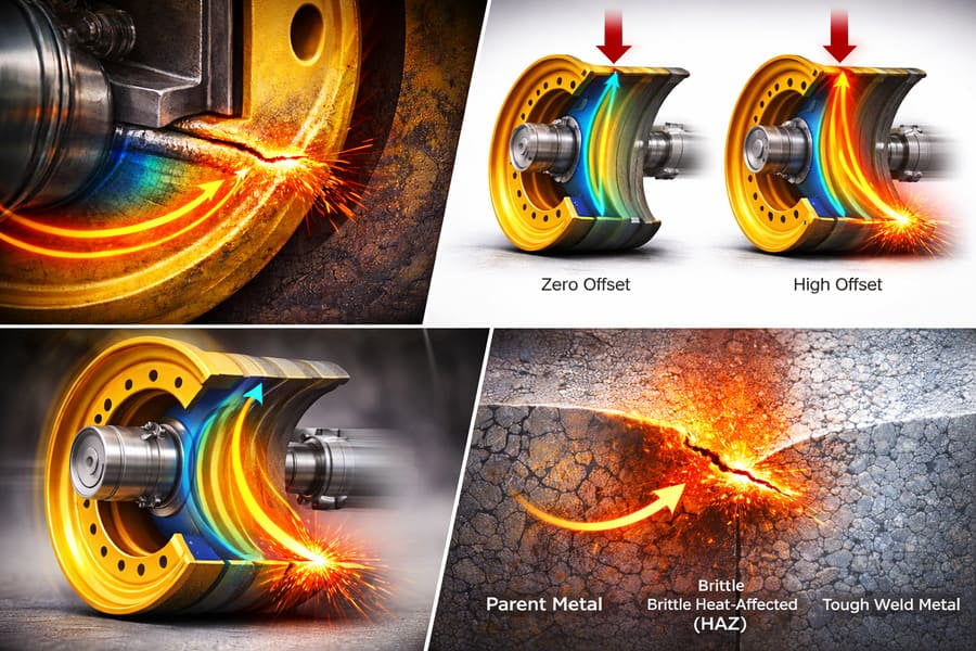
An increased offset3 transforms the disc-rim connection from a simple joint into a high-stress4 hinge. It concentrates the machine's entire bending force5 onto the weld1 and its surrounding Heat-Affected Zone (HAZ)6, making this area the primary point of failure.
For years, I've had procurement managers show me photos of failed wheels, pointing to cracks near the weld1 and blaming "poor Chinese quality." I understand the frustration. But then I ask them a simple question: "Have you changed the offset3 on these OTR wheel2s?" Often, the answer is yes. The truth is, that weld1 didn't just fail; it was forced into a role it was never designed for. The real culprit wasn't the weld1er's skill, but the physics of offset3 that turned a strong joint into a ticking time bomb. Let's break down what's really happening.
How Does Offset Turn the Weld into a Stress Magnet?
A wheel looks like it carries weight straight down through the tire. Why would moving the disc a few inches sideways suddenly focus all that force on one specific weld1ed seam?
Offset creates leverage. This lever action doesn't push down; it tries to bend the disc away from the rim. The weld1 is the fulcrum of this lever, meaning all that bending energy gets concentrated right at the disc-rim joint instead of being distributed.
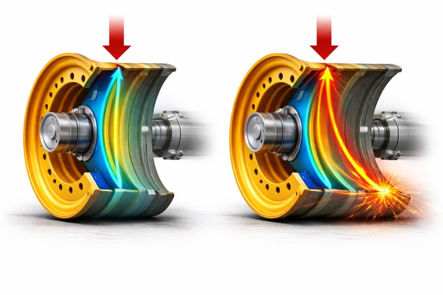
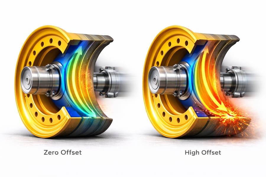
Imagine holding a heavy weight close to your body. It's manageable. Now, hold that same weight with your arms fully extended. The strain on your shoulders is immense. The OTR wheel2 disc is your shoulder, the machine's weight is the heavy object, and the offset3 is the length of your arm. With zero offset3, the load passes down relatively straight. With a large offset3, the load is "held out," creating a powerful bending force5 that tries to pry the disc from the OTR rim. The single point holding them together against this prying force is the circular weld1. It becomes the most stress4ed part of the entire structure. A well-designed OTR wheel2 accounts for this, but an unapproved change in offset3 overloads this system, turning the weld1 into a magnet for stress4.
Is the Weld Just Holding Parts Together, or Is It Doing More?
Most people think a weld1's only job is to join two pieces of metal. As long as it's a solid connection, it should be fine, right? This thinking misses the hidden role it's forced into.
Under offset load7tps://arxiv.org/pdf/2206.14075)3 load, the weld1 zone is no longer just a static joint; it becomes an active bending hinge. With every rotation of the OTR wheel2, the entire structure flexes, and the weld1 area is forced to bend and unbend, accumulating fatigue damage8.
Think of it like this: a door hinge isn't just a connector; it's designed to pivot. A OTR wheel2's weld joint9ps://gescomaxy.com/what-we-automatically-reject-3-otr-rim-designs-that-never-pass-our-internal-review/)1 joint is not designed to be a hinge. It's meant to be a rigid, fixed connection. When you introduce a high offset3, the bending force5s become so great that the OTR rim disc and OTR rim assembly starts to flex. The path of least resistance for this flex is the transition point between the thick disc and the thinner rim—precisely where the weld1 is. So, with every single turn of the wheel under load, this area is subjected to a micro-bend. It's like bending a paperclip back and forth. Even though the weld1 itself is strong, the constant bending action fatigues the metal around it until a crack finally starts.
If the Weld is Strong, Why Do Cracks Start Near It?
Often, when you examine a failure, the crack isn't in the weld1 metal itself but right next to it, in the parent metal10 of the disc or rim. Why would a weaker spot exist right beside a strong weld1?
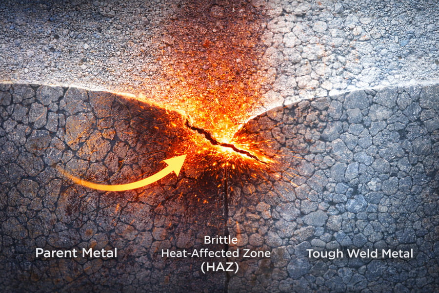
This is due to the Heat-Affected Zone (HAZ)6. Welding heat alters the steel's molecular structure in the area directly next to the weld1, making it more brittle and susceptible to fatigue. This weakened HAZ, now under intense bending stress4 from the offset3, becomes the perfect place for cracks to start.
Welding isn't just gluing metal together; it's a high-temperature process. The intense heat required to melt the steel and filler rod also bakes the metal immediately surrounding the weld1. This "baking" changes the grain structure of the steel, creating the HAZ.
The Three Zones of a Weld Joint
| Zone | Characteristics | Role in Failure |
|---|---|---|
| Weld Metal | Often strong and tough, designed for fusion. | Rarely the point of failure if done correctly. |
| Heat-Affected Zone (HAZ)6 | Brittle, with altered grain structure. | The most common point for fatigue crack initiation11. |
| Parent Metal | The original, unaffected steel of the disc or rim. | Stronger and more ductile than the HAZ. |
Think of the HAZ as the scorched edge of a piece of paper. The paper itself is flexible, but the burnt edge is brittle and will crack easily. When an offset load7tps://arxiv.org/pdf/2206.14075)3 load repeatedly flexes the weld joint9ps://gescomaxy.com/what-we-automatically-reject-3-otr-rim-designs-that-never-pass-our-internal-review/)1 joint, the stress4 will find this weakest point—the HAZ—and initiate a crack.
Is It a Bad Weld or a Bad Offset?
Seeing a crack at the weld1, it's easy to jump to conclusions and blame the supplier for a faulty product. But how can you tell the difference between a true weld defect12s://gescomaxy.com/what-we-automatically-reject-3-otr-rim-designs-that-never-pass-our-internal-review/)1 defect and a fatigue failure caused by offset3?
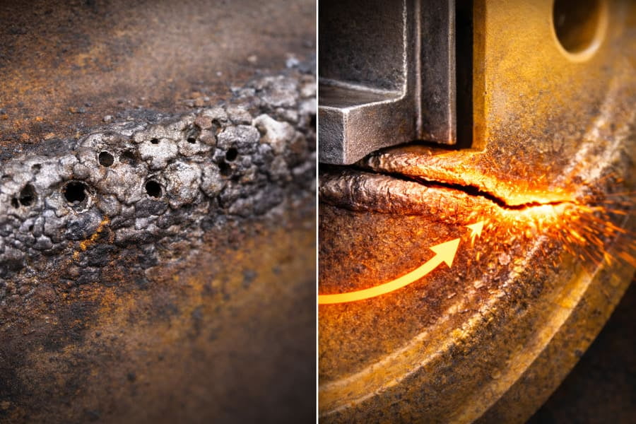
A bad weld1 often fails quickly and may show signs like porosity or lack of fusion. An offset3-driven failure is a classic fatigue crack that grows over time, typically starting in the HAZ. The problem isn't the weld1's quality, but that the wheel's design couldn't handle the applied offset3.
As a supplier with over 12 years of experience and ISO 9001 certified production lines, we take weld quality13://gescomaxy.com/what-we-automatically-reject-3-otr-rim-designs-that-never-pass-our-internal-review/)1 quality extremely seriously. We use precise robotic weld1ing and conduct rigorous inspections. A true weld1ing defect is rare. The failures I see in the field are almost always fatigue cracks. They look clean, they start from a single point, and they grow progressively. This is the signature of an overloaded system. When you use a OTR wheel2 with an offset3 it wasn't designed for, you are fundamentally changing the engineering of your equipment. The resulting failure isn't a sign of a bad part; it's a sign that the application and the design were mismatched. The weld1 is just the messenger, delivering the bad news that the physics of offset3 were ignored.
Conclusion
The weld1 zone is where the leverage of offset3 becomes a destructive force. It turns the joint into a bending hinge, and the weakened HAZ becomes the starting point for fatigue cracks.
Exploring weld quality can provide insights into maintaining strong and reliable wheel connections. ↩
Exploring common OTR wheel issues can help in making informed procurement decisions. ↩
Understanding offset's role can help prevent future wheel failures and improve design. ↩
This resource can explain how stress impacts welds and help in designing better joints. ↩
Understanding bending forces can aid in designing more resilient OTR wheels. ↩
Learning about HAZ can help you understand its impact on weld integrity and failure points. ↩
Understanding offset load is crucial for designing wheels that can withstand stress. ↩
This link can provide valuable information on preventing fatigue in welded joints. ↩
This resource can help you learn how to assess and improve weld quality. ↩
Understanding parent metal properties can enhance your knowledge of weld performance. ↩
Exploring crack initiation can help in identifying potential failure points in designs. ↩
This link can provide guidance on distinguishing between weld defects and fatigue failures. ↩
Understanding factors affecting weld quality can lead to better manufacturing practices. ↩