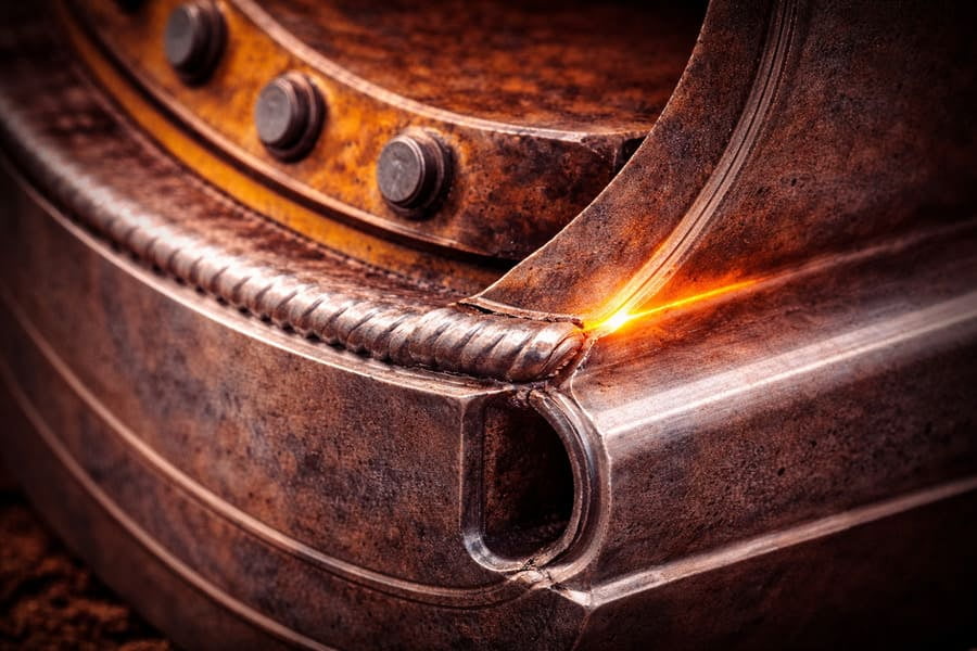
You see a heavy-duty rim with extra steel plates and thick ribs welded on. It looks incredibly strong, like it could handle anything. But then it fails, with a crack starting right at the edge of that "reinforcement."
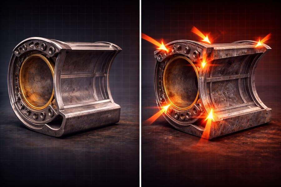
Poorly designed reinforcements create abrupt changes in stiffness. Instead of flowing smoothly through the structure, stress concentrates at these "stiffness jumps," creating a weak point that becomes a hotbed for fatigue cracks1. The OTR rim reinforcement2 itself creates the failure point.
I remember a client from a large quarrying operation sending me photos of a failed OTR rim. A massive, thick gusset plate3 had been welded onto the back section to "strengthen" it. The crack wasn't on the gusset or far away from it; it ran perfectly along the weld line4 where the gusset ended. He was baffled. "We added steel to make it stronger, and it broke right there!" he said. I had to explain that by adding that plate, they had inadvertently built a "stress wall." All the flexing forces that should have flowed through the rim slammed into that rigid edge, concentrating there until the steel gave up. The fix made the problem worse.
Why Do Cracks Form Right Next to Reinforcements?
You add a reinforcing rib to a high-stress area5, expecting to solve a problem. Instead, a crack appears right beside your solution, making you wonder if the effort was counterproductive.
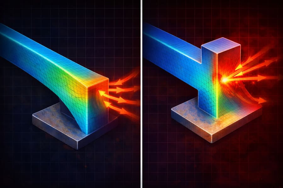
The edge of a reinforcement creates an abrupt change from flexible to stiff. Stress energy cannot transfer smoothly across this boundary. It reflects and concentrates at the edge, creating a fatigue hotspot that fails much faster than the surrounding metal.
Think of how water flows in a river. If the riverbank is smooth and curved, the water flows past it easily. But if you build a solid concrete wall that juts out into the river, what happens? The water slams into the corner of the wall, creating turbulence and intense pressure. Metal stress behaves in a similar way. A good rim design allows stress to "flow" through the structure like water in a smooth river. Adding a sudden, blocky reinforcement is like building that concrete wall. The stress can no longer flow smoothly. It "crashes" against the edge of the stiff section, amplifying its force right at that point.
Is a Thicker Rim Always a Stronger OTR Rim?
You're designing or specifying a OTR rim for a tough job, so you ask for thicker steel6. It seems like a simple and logical way to increase strength and durability.
No, a sudden increase in thickness can be more dangerous than a thinner, uniform plate7. Abrupt changes in thickness create stress concentrations8. A gradual, smooth transition in thickness is far more effective at extending fatigue life.
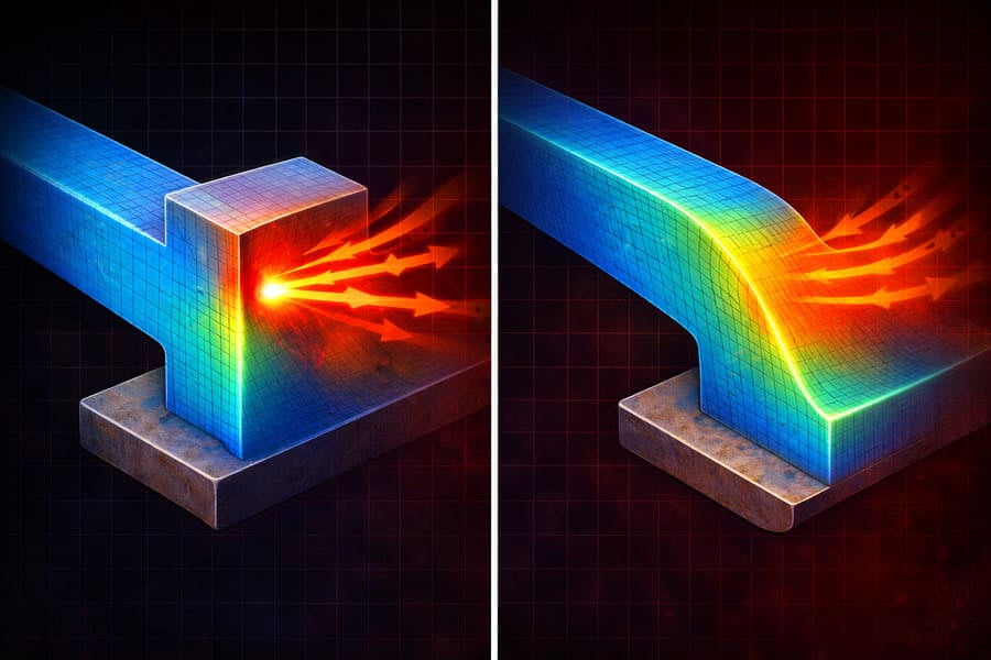
This is one of the biggest misconceptions in heavy equipment design. Making something thicker only helps if the stress can get to that thicker section smoothly. If you have a 10mm plate that abruptly transitions to a 20mm plate, the point of transition becomes the new weak link. All the flex from the thinner section gets concentrated right at that sharp corner.
The Impact of Geometric Transitions
| Design Approach | Stress Flow | Fatigue Life | Failure Risk |
|---|---|---|---|
| Abrupt Thickness Change | Obstructed, Concentrated | Short | High |
| Gradual, Tapered Change | Smooth, Distributed | Long | Low |
| Uniform, Thinner Section | Evenly Distributed | Moderate | Moderate |
For over 12 years, I've seen countless failures caused by this exact issue. A better design might use a 12mm plate everywhere, or taper smoothly from 10mm to 15mm over a long distance. It might not look as "strong" at first glance, but by managing the stress flow9, it will last much longer.
Can a Rim That 'Looks Stronger' Actually Be More Dangerous?
You're comparing two OTR rims. One is sleek and smooth. The other is covered in gussets and extra plates, looking much more rugged and tough. You instinctively lean toward the one that looks "beefier."
Yes, OTR rims that "look stronger" often hide dangerous stress concentrations8 created by those very reinforcements. A design that appears visually robust can have a much shorter fatigue life than a cleaner, more intelligently designed structure that manages stress flow9 properly.
This is the great paradox of OTR wheel design. The things people add to make a OTR rim look strong are often the very things that make it fail. Why? Because those blocky gussets and sharp-edged plates create stiffness jumps. Each one is a potential starting point for a crack. A truly strong OTR rim is often one that looks deceptively simple. Its strength comes from intelligent geometry, gradual changes in thickness, and smooth, flowing lines that distribute stress evenly across the entire structure. It doesn't need to look like a fortress because it has been engineered not to have any single weak points. When a customer sends me a drawing of a proposed "heavy-duty" design covered in gussets, my first job is often to explain how we can make it stronger by removing half of them and smoothing out the transitions.
How Do You Design a OTR Rim That Manages Stress Properly?
If adding steel isn't the answer, how do you create a genuinely strong OTR rim that can withstand extreme forces without creating hidden weak points?
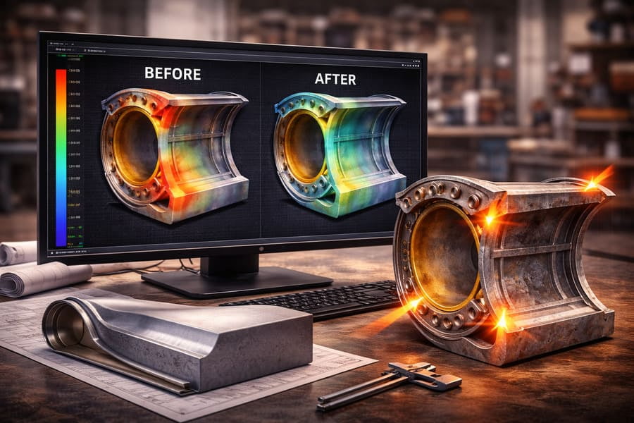
A robust design is achieved through holistic engineering, not by adding parts. It requires using Finite Element Analysis (FEA)10 to simulate stress, then creating smooth, gradual transitions in geometry and thickness to ensure stress flow9s without concentrating at any one point.
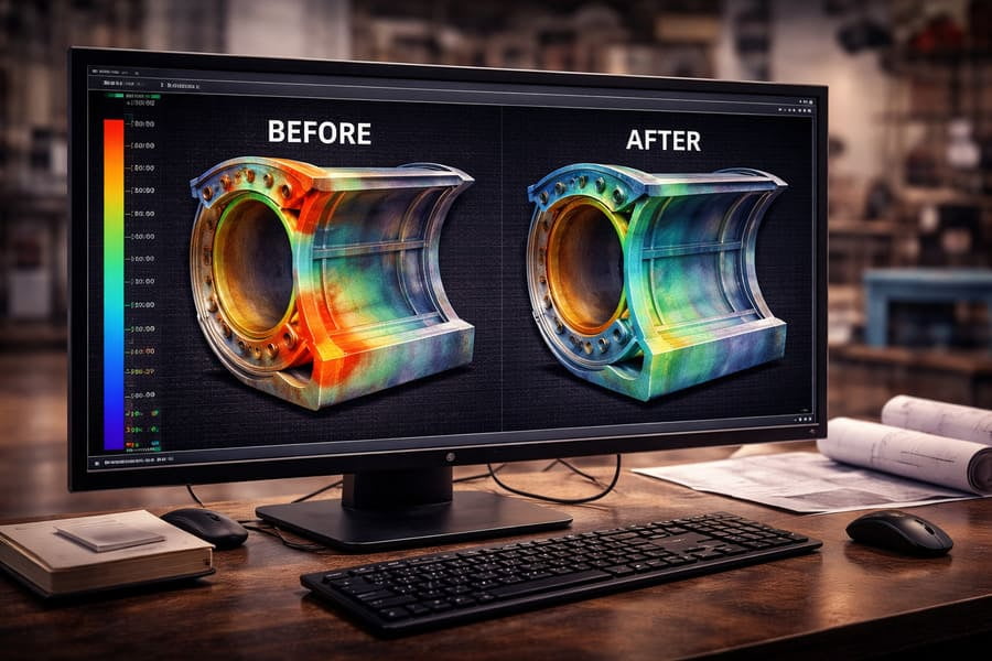
You can't guess where stress will go. You have to calculate it. This is where modern tools are essential. At Gescomaxy, we don't just weld more steel on. We start with an FEA model. We apply the customer's specific loads—the weight, the cornering forces, the braking torque. The computer simulation shows us exactly where the stress hotspots11 are, colored in bright red. Our job as engineers is then to redesign the rim to eliminate those red spots. This means smoothing a corner here, gradually tapering a section there, and ensuring the entire structure works as one system. This process creates a rim that is strong everywhere, rather than a rim that has strong parts and very weak points in between them.
Conclusion
A truly strong rim isn't the one with the most reinforcements. It's the one with the smoothest transitions, designed to distribute stress, not just block it. True strength is invisible.
Exploring the causes of fatigue cracks can enhance your understanding of material integrity. ↩
Understanding the best practices can help prevent failures and improve rim durability. ↩
Gusset plates can be beneficial or detrimental; understanding their role is key to good design. ↩
Understanding weld line issues can help in designing more reliable and durable structures. ↩
Identifying high-stress areas is essential for effective design and failure prevention. ↩
Explore the misconceptions about thickness and strength in engineering materials. ↩
Uniform plates can provide better stress distribution and reduce failure risks. ↩
Learn how stress concentrations can lead to failures and how to mitigate them in designs. ↩
Learn how effective stress flow can enhance the longevity and safety of structures. ↩
FEA is crucial for predicting stress points and optimizing designs for better performance. ↩
Identifying and mitigating stress hotspots is crucial for enhancing structural integrity. ↩