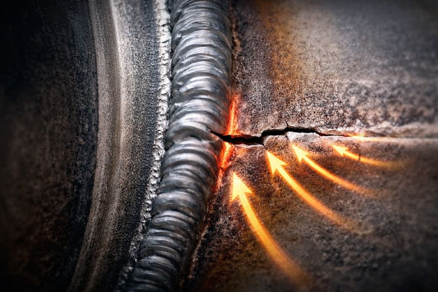
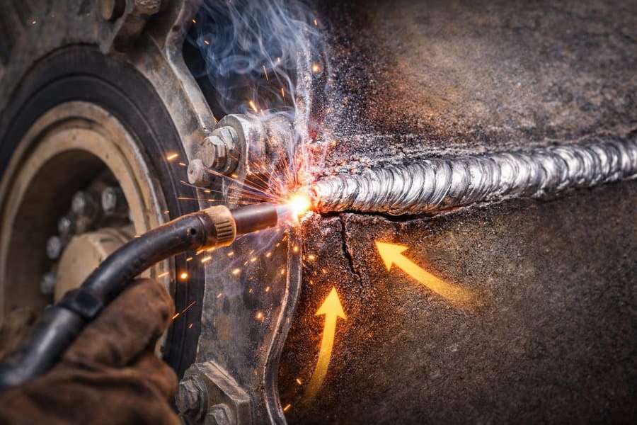
You see a cracked weld1 on an OTR wheel and immediately blame the supplier's welding quality2. But the replacement wheel fails the same way, wasting money and causing critical project delays.
Welded zones crack first not because the weld is inherently the weakest point, but because the wheel's geometry concentrates immense operational stress3 (bending moment4) directly onto that specific area. The weld is simply the location where the design-induced stress becomes visible as a failure.
Over my 13 years in this business, I've stood in countless workshops with frustrated fleet managers pointing to a fracture right along the weld seam. Their first instinct is always the same: "It's a bad weld." It's a logical assumption, but it's almost always wrong. The real conversation shouldn't be about the quality of the weld, but about the forces that the wheel's design forces that weld to handle. Understanding this difference is the key to solving the problem permanently instead of just replacing one doomed wheel with another.
Why Does the Weld Take All the Blame for Cracks?
You operate heavy machinery, and you know that a chain is only as strong as its weakest link. So, when a weld cracks, you logically identify it as the weak link causing the failure.
The weld isn't the weakest link; it's the focal point of stress. The fundamental structure of an OTR wheel is designed to transfer massive loads, and this design naturally concentrates bending forces at the junction between the rim and the disc—right where the weld is.
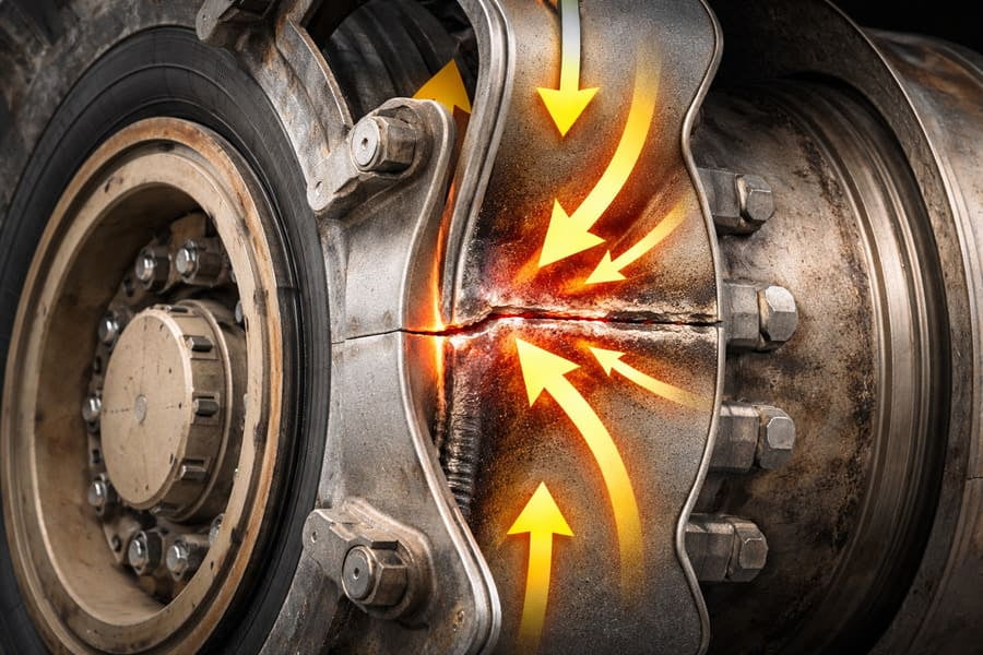
Think of a lever. The further you are from the fulcrum, the more force you can apply. An OTR wheel acts in a similar way. The weight of the vehicle and its load pushes down on the disc, while the ground pushes up on the rim. This creates a powerful bending moment4 that peaks at the point where the disc connects to the OTR rim. This junction is, by necessity, the welded zone. The weld isn't failing because it's poorly done; it's failing because it's located at the epicenter of the OTR wheel's highest structural stress. It’s like blaming a single rivet for a bridge collapse when the real issue was the overall design that put too much stress on that one point. A perfect weld subjected to forces beyond its design limits will still fail.
Structural Stress Points
| OTR Wheel Component | Primary Function | Role in Stress Concentration |
|---|---|---|
| Disc | Transfers torque from the axle | Acts as the long arm of the lever |
| Rim | Holds the tire and contacts the ground | Provides the counter-force |
| Weld Zone | Joins the disc and rim | Sits at the point of maximum bending moment4 |
How Does a Perfect Weld Create a Natural Weak Point?
You've specified a wheel with high-quality welding, expecting it to be robust. Yet, you still see failures initiating near the weld, which seems to defy logic and your quality requirements.
The welding process itself creates a "stiffness transition zone." The extremely rigid weld metal, combined with the slightly altered Heat-Affected Zone (HAZ)5 next to it, forms a boundary that naturally attracts stress and becomes the starting point for fatigue cracks6.
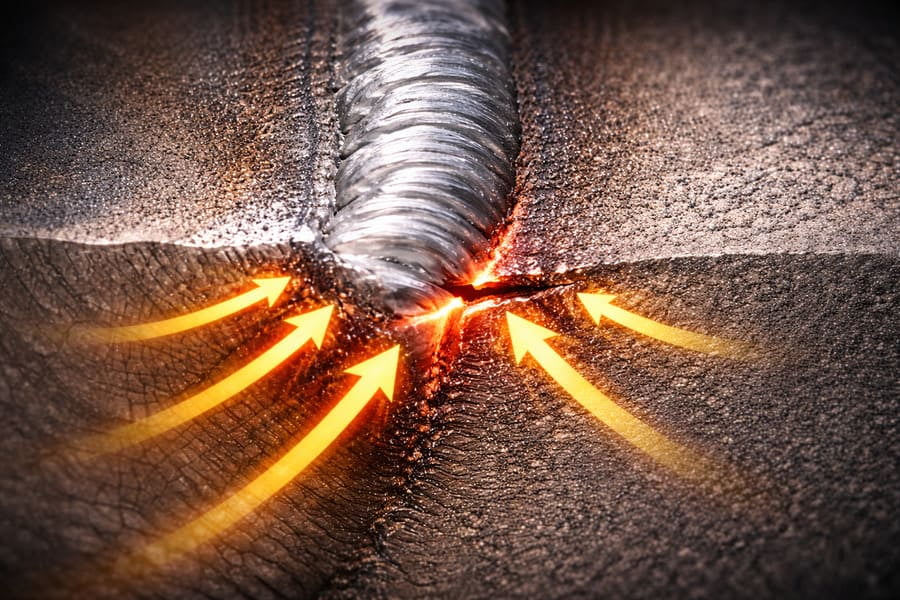
When you weld two pieces of steel, you're not just joining them; you're creating a new metallurgical reality. The weld bead itself is very hard and stiff. The area immediately next to it, the HAZ, has had its crystal structure altered by the heat, making it different from the original parent metal. This creates a gradient of stiffness: very rigid weld, slightly less rigid HAZ, and the original stiffness of the parent metal. When the wheel flexes under load, this transition zone acts like a hinge. Stress will always find the path of least resistance, and this change in stiffness provides that path. Even with a flawless, perfectly penetrated weld, this microscopic transition zone exists. Over millions of cycles of flexing, tiny fatigue cracks6 form here first and then grow. So, ironically, the process of creating the joint also creates the perfect environment for a crack to begin.
Are We Asking the Right Question About OTR Wheel Failures?
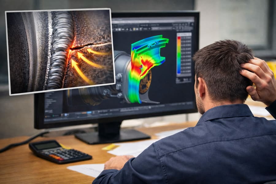
Your team's failure analysis7 focuses on weld penetration8, porosity, and other welding defects9. While important, this approach often misses the bigger picture and leads to the wrong conclusions.
The industry mistakenly treats the crack's location as the root cause. The right question isn't "Why did the weld crack?" but "What forces in the system caused stress to concentrate at the weld's location?"
This is the most common engineering misjudgment I see. It's a classic case of confusing correlation with causation. The crack is at the weld, so the weld must be the cause. This leads down a rabbit hole of inspecting welding procedures, demanding more certifications, and arguing with suppliers over microscopic details. While good welding is non-negotiable, it doesn't solve the core problem. The correct approach is to step back and look at the entire system. Was the machine overloaded? Were the tires incorrect for the application, transferring excessive shock to the wheel? Or, most often, is the wheel's fundamental design (the shape and thickness of the disc and rim) creating a stress concentration10 that no weld can withstand indefinitely? Focusing on the weld is like blaming a dam for breaking at one spot without asking if the reservoir behind it was overfilled.
Can a Stronger Weld Fix a Flawed OTR Wheel Design?
Your instinct is to demand a stronger weld—thicker beads, different filler material, more extensive quality checks. You believe this will reinforce the wheel and prevent future cracks from occurring.
No. Using a better or stronger welding technique on a poorly designed wheel is only a temporary fix. It may slightly delay the failure, but it cannot correct a flawed load path11 that is channeling destructive force into one small area.
This is the improvement blind spot. If the geometry of the OTR wheel disc and OTR rim is designed in such a way that it creates a massive stress riser12 at the weld joint, you can use the strongest weld in the world, and it will eventually fail. It might last 10% longer, but the failure is pre-programmed by the design. The only true solution is to redesign the OTR wheel to distribute the stress more evenly. This could involve using a thicker disc, changing the angle where the disc meets the OTR rim, or using advanced manufacturing techniques13 like flow-forming to create a stronger, more seamless transition. As a procurement manager, this means your focus should shift. Instead of just qualifying a supplier's welding process, you need to qualify their engineering and design capabilities. A good partner like Gescomaxy helps you analyze these failures to understand the root cause, ensuring the replacement parts are engineered to succeed.
Conclusion
Stop blaming the weld. The crack in an OTR wheel is a message from the machine about stress and design. Understanding this root cause is the first step to building a truly reliable fleet14.
Explore this resource to understand the underlying issues behind cracked welds and how to prevent them. ↩
Learn about the impact of welding quality on OTR wheel durability and performance. ↩
Discover how operational stress affects the integrity of OTR wheels and leads to failures. ↩
Gain insights into bending moments and their significance in wheel design and performance. ↩
Learn about the Heat-Affected Zone and its effects on weld integrity and performance. ↩
Discover the mechanisms behind fatigue cracks and how to mitigate them in welded structures. ↩
Explore the importance of failure analysis in engineering to prevent future issues. ↩
Understand the significance of weld penetration in ensuring strong and reliable joints. ↩
Learn about common welding defects and how they can affect the performance of welded components. ↩
Understand stress concentration and its role in mechanical failures, particularly in OTR wheels. ↩
Gain insights into load paths and their importance in ensuring structural integrity. ↩
Explore the concept of stress risers and their implications for mechanical design. ↩
Discover advanced manufacturing techniques that can enhance the performance of OTR wheels. ↩
Explore strategies for building a reliable fleet, focusing on design and engineering. ↩