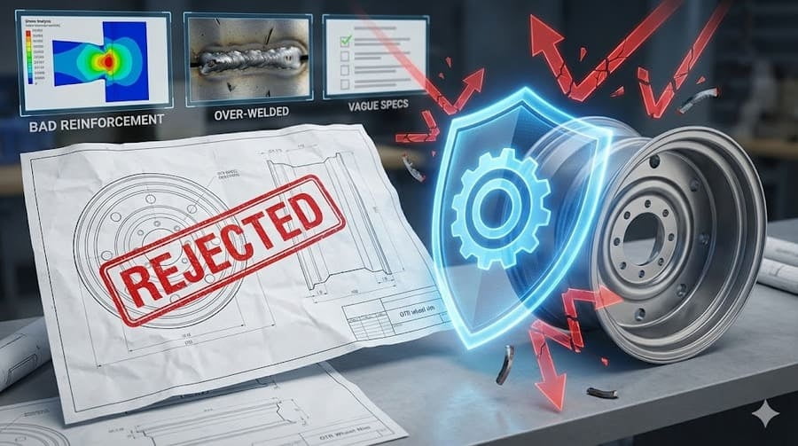
You send us a technical drawing for a custom OTR rim, confident it meets your needs. But we reject it. This can be frustrating, leaving you questioning our capability or flexibility.
We automatically reject OTR rim designs1 with misplaced reinforcements2 that concentrate stress, excessive welds3 that add failure points without improving load paths4, and designs with generic specs but no clear application scenario5. These are not conservative choices; they are critical for long-term risk control.
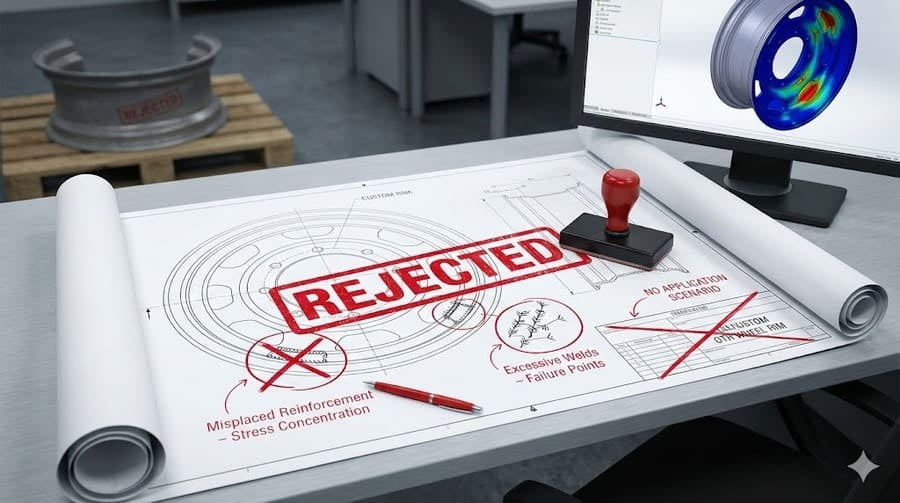
Saying "no" to an order might seem like bad business, but after more than 12 years in this industry, I've learned that saying "yes" to a bad design is far worse. A failed rim on a customer's site is a failure of our responsibility. Our internal review isn't a barrier; it's a shield. It's our commitment to you that we won't just manufacture your design; we will validate it against the unforgiving laws of physics. Let's explore the three common design traps we always reject to protect our clients' investments and reputations.
Isn't a Beefier Rim Always a Stronger Rim?
You've requested extra reinforcement plates on a rim, thinking more steel equals more durability. But we reject the design, telling you it’s weaker. This seems to defy logic.
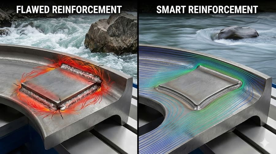
Adding structural material is meaningless if it amplifies stress concentration6. Reinforcing the wrong places often creates stiff, inflexible points that focus fatigue, accelerating cracking and leading to premature failure. More material can actually increase risk.

Think of a river. If you place a large, rigid boulder in the middle, the water doesn't stop. It violently crashes against the boulder, eroding it and the riverbed around it. The same thing happens with stress in a steel rim. Stress needs to flow smoothly through the structure. When you weld a thick, stiff plate onto a flexible area, you create a "stress boulder." All the operational forces, instead of distributing evenly, concentrate on the edges of that reinforcement. This is where fatigue cracks start. It’s a classic case where the "fix" actually causes the failure. Our job is to ensure reinforcement dissipates energy, not concentrates it.
Smart vs. Flawed Reinforcement
Our internal engineering review is focused on how stress flows, not just how much material is there. A good design helps the rim flex and distribute load; a bad one creates a breaking point.
| Feature | Smart Reinforcement (Our Standard) | Flawed Reinforcement (We Reject) |
|---|---|---|
| Goal | Distribute stress across a wider area | Add bulk to a specific spot |
| Design | Tapered edges, smooth transitions | Sharp corners, abrupt thickness changes |
| Effect | Reduces stress concentration6 points | Creates new, high-stress concentration6 points |
| Result | Increased fatigue life7 and overall durability | Reduced fatigue life7, predictable failure at weld edges |
True strength comes from intelligent design, not just adding weight.
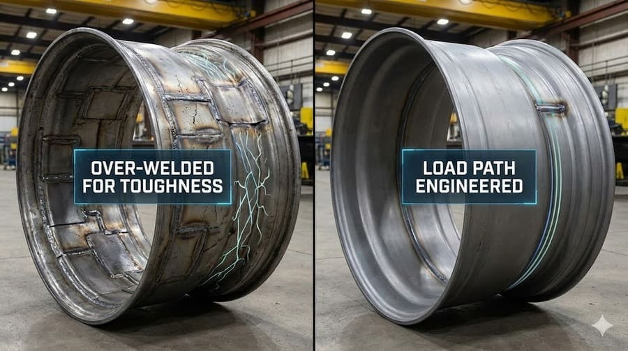
Doesn't More Welding Mean a Tougher Rim?
You see a complex design with multiple weld seams and assume it's built for extreme strength. So you're surprised when we propose a simpler design with fewer welds.
More welds do not equal higher strength if the primary load path remains unchanged. In many cases, unnecessary welds simply create more heat-affected zones8 (HAZs)—brittle areas prone to cracking—which become potential points of failure.
I once had a client who was very proud of a rim design he called "over-welded for toughness." It looked impressive, like a patchwork of steel plates. But our analysis showed that the actual forces from the vehicle's load would only travel through two main weld seams. All the other welds were just along for the ride. They carried no significant load but introduced a dozen new heat-affected zones8. Each time you weld, you change the crystal structure of the steel near the seam, making it harder but more brittle. So, his "tough" rim was actually a minefield of potential cracks waiting to happen. We redesigned it to align the welds with the true load path, increasing strength while reducing failure points.
The Purpose of a Weld
A weld's only job is to transfer load. If it's not doing that efficiently, it's a liability.
- Load Path Engineering: Our first step is always to map the load path. Where does the force from the ground go? How does it travel through the rim to the axle? Every weld must be a critical bridge on this path.
- Minimizing Heat-Affected Zones (HAZ): Fewer welds mean less brittle material. A simpler, cleaner design is often a stronger one.
- Weld Quality over Quantity: We focus on the quality and placement of a few critical welds rather than the number of seams. A single, well-placed, full-penetration weld is infinitely stronger than three decorative ones.
Isn't Matching the Specs Enough?
You provide a list of parameters: diameter, width, bolt pattern, and load rating. It seems complete. But we come back with more questions: "What machine? What terrain? What's the duty cycle9?"
Matching parameters without a clearly defined application scenario5 is not engineering; it's just clerical work. When operating conditions are vague, the risk of validating the design is pushed downstream—directly onto you, the end-user.
This is perhaps the most important rejection criteria we have. A rim that is perfectly safe for a container handler in a smooth port will fail catastrophically on a dump truck in a quarry, even if they share the same basic dimensions and load rating. The port machine experiences steady, cyclical loads. The quarry truck experiences brutal, high-frequency impacts combined with torsional stress. Simply "matching the specs" ignores this crucial context. We refuse to build a rim when we don't know its true purpose. Asking detailed questions isn't about being difficult; it's about taking shared responsibility for the outcome.
Application is Everything
A spec sheet10 is a starting point, not a solution. To ensure reliability, we need to know the story behind the numbers.
| Vague Parameter | Our Clarifying Question | Why It Matters |
|---|---|---|
| Load Capacity: 15 Ton | Static or dynamic? Average or peak? | A rim must handle peak impact loads, not just average weight. |
| Application: Mining | Surface or underground? Hard rock or soft soil? | Determines the type of impact and abrasive wear the rim will face. |
| Vehicle Speed: 30 km/h | Constant speed or stop-and-go? | Affects heat buildup and fatigue cycles, especially in the bead seat area. |
Refusing to proceed without this data is our commitment to preventing a field failure11 before the first piece of steel is ever cut.
Conclusion
Rejecting a flawed OTR rim design isn't a negative response; it's our most fundamental act of quality control and commitment to our clients' long-term success and safety on site.
Understanding common design flaws can help you avoid costly mistakes in your projects. ↩
Learn how proper reinforcement placement can enhance the durability of your designs. ↩
Discover why too many welds can compromise the integrity of your rim. ↩
Understanding load paths is crucial for creating safe and effective rim designs. ↩
Learn how application context can prevent design failures and enhance safety. ↩
Explore the effects of stress concentration on materials to improve your designs. ↩
Learn how to enhance the fatigue life of your designs for better performance. ↩
Understanding HAZ can help you make better welding decisions in your projects. ↩
Understanding duty cycles can help you design rims that withstand real-world conditions. ↩
A comprehensive spec sheet is essential for successful engineering and design. ↩
Understanding the causes of field failures can help you avoid them in your projects. ↩