A OTR cracked wheel looks like random, expensive bad luck. But what if every crack is a map, telling you exactly what went wrong with the design and why it failed?
OTR wheel cracks1 are not random. They are a visual language of stress2, following predictable paths that reveal the wheel's true structural weaknesses, load paths, and stiffness imbalances3. By learning to read them, you can diagnose fundamental design flaws4.
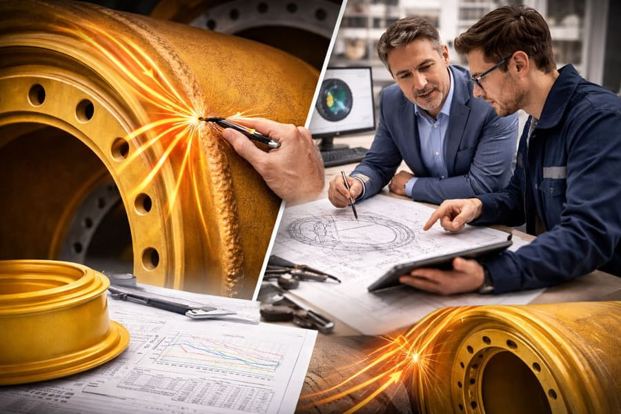
I've spent over 12 years looking at failed wheels, not just as a trader but as a student of engineering. They're not just scrap metal; they're textbooks. Each crack tells a story about the forces the wheel endured and how its design managed—or failed to manage—them. It's a skill every procurement manager5 should understand because it turns a costly failure into valuable data. It helps you ask better questions of your suppliers. Let's start by decoding what these patterns are telling us.
Why Do Cracks Follow Predictable Paths Instead of Appearing Randomly?
You see a crack and assume it's just a weak spot that finally gave way. But the crack's precise location and direction are not a coincidence; they are a direct result of physics.
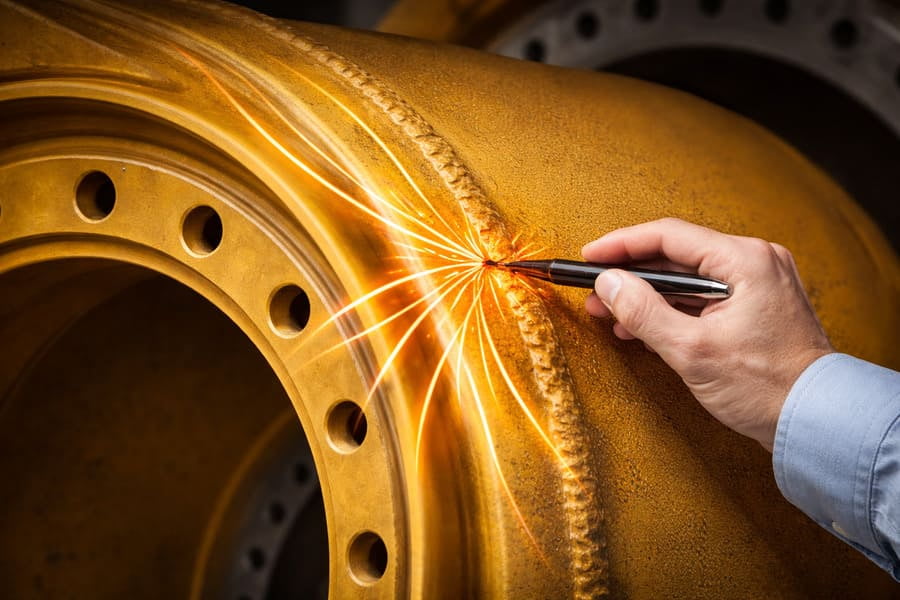
Cracks follow the path of least resistance6 along the routes of highest stress. The direction and location of the crack show exactly how energy and force are flowing through the wheel's structure, seeking out the weakest point in the design's load path.
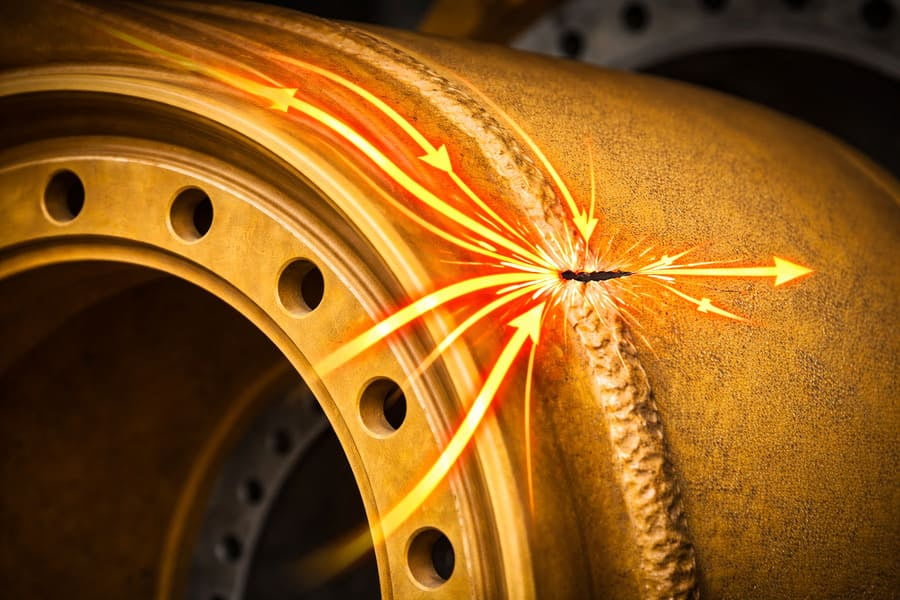
Think of stress in a OTR wheel like water flowing through a landscape. The water will always find the easiest and fastest path downhill, carving a channel as it goes. In a wheel, stress concentrates around changes in shape—like welds, bolt holes, or where the disc meets the OTR rim. These are the areas of highest energy. A fatigue crack7 is simply the physical result of the steel failing along that high-energy path after repeated loading. It's not a random event. The crack grows in a direction that relieves the most stress, which is why its path is so telling. It’s a physical map of the forces at work. By understanding this, you stop seeing a failure and start seeing a data point.
Common Crack Paths and Their Meanings
The location tells you a lot about the type of force that caused the failure.
| Crack Location | Likely Cause (Force) | What It Tells You About the Design |
|---|---|---|
| Circumferential at Weld Toe | Bending Stress | Classic fatigue from load and flex; may indicate a stiff disc8. |
| Between Bolt Holes | High Clamping Force | Incorrect torque or issues with the mounting surface. |
| Radial from Disc Center | Torsional/Twisting Stress | High torque from acceleration/braking is overwhelming the disc. |
| On the OTR Rim Flange | Impact or Overload | Caused by hitting obstacles or exceeding the load/pressure rating. |
How Can a Crack Reveal a OTR Wheel's Hidden Structural Flaws?
A OTR wheel looks like one solid piece of steel. How can you tell if one part is too stiff or another is too weak just by looking at a crack on its surface?
A crack pattern is a direct reflection of stiffness distribution. Cracks don't appear on the strongest parts; they appear where stress is concentrated because another part is too stiff and isn't sharing the load properly.
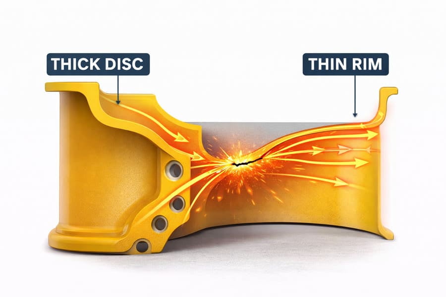
I often see wheels where the customer demanded a very thick disc for "strength." The result? The disc itself never breaks, but cracks appear all around the welds connecting it to the rim. The crack is telling you that the disc is too rigid. It's not flexing and sharing the load with the rest of the wheel. Instead, it's acting like a rigid lever, forcing all the bending stress9 into the smaller, weaker area of the weld and the rim. The crack exposes this imbalance. A well-designed wheel works like a team, with every part carrying its fair share of the load. A crack is a sign that one part of the team isn't doing its job, forcing another part to fail. The location of the crack points directly to the victim of this poor design teamwork.
Reading Stiffness from Crack Location
- Cracks at the Weld: If cracks consistently form at the weld connecting the disc and rim, the disc is likely too stiff. It's pushing stress onto the connection point instead of absorbing it.
- Cracks on the Rim: If the rim itself is cracking away from the disc, it might be too thin or made of a material that can't handle the flex passed on from the disc.
- Cracks on the Disc: If the disc itself cracks (especially radially), it might be too flexible or have stress concentrators10 like sharp corners in its design.
Is Reading Cracks a Real Engineering Skill?
This might sound like reading tea leaves. You might wonder if this is just a story we tell after a failure, or if it's a real, diagnostic engineering practice.
Yes, this is a core principle of failure analysis11. A crack is engineering language, not a coincidence. Its characteristics communicate the wheel's design logic and performance under load more clearly than many lab test reports can.
In our ISO 9001-certified process, we use advanced tools like Finite Element Analysis (FEA)12 to predict where stress will concentrate. When we see a failed wheel in the field, the crack pattern is real-world validation of those models. If a crack appears where the FEA predicted high stress, it confirms the design's behavior. If it appears somewhere unexpected, it gives us critical new information to improve the design. A lab report might tell you a wheel survived one million cycles. But a crack tells you why it failed on the one-million-and-first cycle. It shows you the precise weak point, the direction of force, and the failure mode. As a procurement manager5, understanding this helps you partner with suppliers like us who don't just sell wheels, but who read this language to build better, more reliable products for you.
How Does This Knowledge Help You Procure Better OTR Wheels?
Understanding that cracks are a language is interesting, but how does it help you make better purchasing decisions and reduce your fleet's operating risk?
It empowers you to have deeper conversations with your suppliers. Instead of just discussing price and thickness, you can ask about their design philosophy13 for managing stress and preventing the very crack patterns you've seen.

When a wheel fails, your first instinct might be to blame the quality and find a cheaper supplier. But now you can look at the crack and ask a more intelligent question. You can go to your supplier and say, "We are seeing circumferential cracks at the weld toe. This suggests a stiffness issue. How does your design mitigate this?" This question shows you understand the mechanics of failure. It pushes the supplier to justify their engineering, not just their price. At Gescomaxy, these are the conversations we want to have. We can show you our FEA models, explain how our disc profiles are shaped to ensure smooth stress transfer, and how our welding procedures are controlled to create a tough, resilient joint. This knowledge transforms you from a buyer into an informed partner, allowing you to select OTR wheels based on engineering logic14, not just specifications on a sheet.
Conclusion
OTR wheel cracks1 are not random accidents. They are the physical language of engineering, revealing the secrets of a wheel's structure, load paths, and ultimate points of failure.
Understanding OTR wheel cracks can help you grasp the engineering principles behind wheel design and failure. ↩
Exploring this concept can enhance your understanding of how stress affects material performance. ↩
Understanding stiffness imbalances can lead to better design choices and material selection. ↩
Learning to diagnose design flaws can improve product reliability and safety. ↩
Exploring the role of a procurement manager can enhance your purchasing strategies. ↩
This principle is crucial for understanding how forces interact with materials. ↩
Exploring fatigue cracks can provide insights into material failure and longevity. ↩
Exploring this can help you understand the trade-offs in material stiffness. ↩
Understanding bending stress is essential for evaluating the strength of materials. ↩
Learning about stress concentrators can improve your ability to predict failure points. ↩
Understanding failure analysis can enhance your skills in diagnosing and preventing failures. ↩
FEA is a powerful tool for predicting stress and improving design accuracy. ↩
Understanding design philosophy can lead to better collaboration with suppliers. ↩
Understanding engineering logic can help you make informed decisions in procurement. ↩