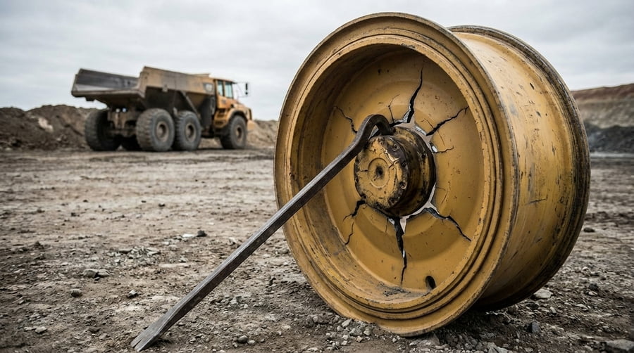
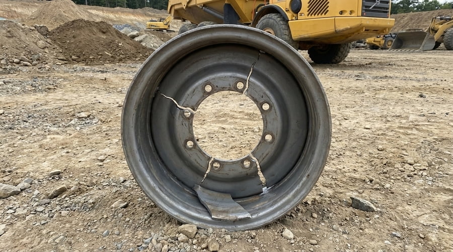
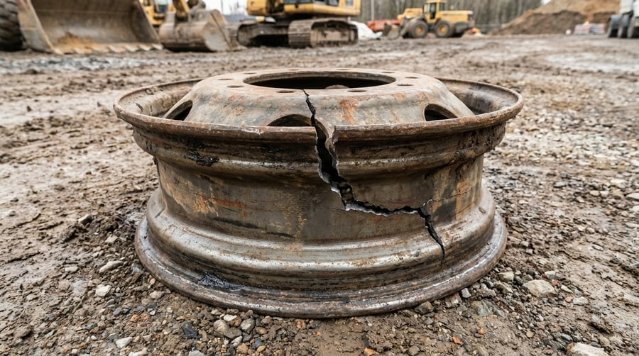
You specified a replacement wheel with the correct bolt pattern and load rating1. It fits perfectly, but it fails prematurely, cracking around the disc. You're left confused, holding a broken part that should have worked.
OTR Wheel offset2 changes the lever arm3 where the vehicle's load applies force. Even a small, incorrect offset dramatically multiplies the bending stress4 on the wheel disc and welds5, rapidly accelerating metal fatigue6 and causing unexpected failures.
I once had a client running a fleet of articulated dump trucks7 in a huge earthmoving project. They were experiencing a series of OTR wheel disc failures on just one side of their fleet. The maintenance manager was frustrated. "These are top-quality OTR rims, rated for the load! Why are they breaking?" he asked. We went through every detail, and finally, we found it. A new batch of rims they had sourced from another supplier had a 20mm greater offset. To the naked eye, they looked identical. But that tiny 20mm shift acted like putting a long pipe on a wrench. It amplified the bending forces on the wheel disc with every single rotation, creating a fatigue nightmare.
How Can Millimeters of Offset Multiply Stress on a OTR Wheel?
You think a few millimeters of difference in OTR wheel offset is a minor detail, barely noticeable on a massive O-T-R machine. But you keep seeing cracks and failures that don't make sense.
Offset is the distance from the wheel's mounting face to the centerline of the tire. This distance acts as a lever. Increasing this lever, even by millimeters, exponentially multiplies the bending force, or "moment," that the wheel disc must endure.
Think about using a wrench to loosen a tight bolt. If you use a short wrench, you have to apply a lot of force. If you put a long pipe over the handle, the bolt becomes easy to turn. That extra length is a lever, and it multiplies your force. OTR Wheel offset2 works the exact same way. The wheel disc is the fulcrum, and the vehicle's weight is the force. The offset is the length of the lever arm3. A small change from, say, 150mm to 170mm might not sound like much. But that extra 20mm increases the bending moment significantly, putting immense stress on the welds5 and the connection point between the disc and the rim base.
The Amplifying Effect of Offset
| Offset Status | Lever Arm Length | Bending Moment | Fatigue Life |
|---|---|---|---|
| Correct Offset | As Designed (e.g., 150mm) | Normal | Expected |
| Incorrect Offset | Increased (e.g., 170mm) | Highly Amplified | Drastically Reduced |
This is why a wheel with the "correct" load rating1 can still fail. The rating assumes the correct offset. Once you change that, all the calculations go out the window.
Does the Rated Load Account for the Wrong Offset?
You carefully select a wheel with a load capacity that exceeds your machine's maximum weight. You believe this safety margin8 protects you, but failures are still happening on machines with the wrong offset.
No. A OTR wheel's nominal load rating1 is calculated assuming the offset is correct. It tests the wheel's ability to handle vertical weight and standard side forces, but it does not account for the massive eccentric bending forces9 created by an incorrect offset.
A load rating1 is a crucial baseline, but it's based on a set of ideal conditions. The standard tests (like those from TRA or ETRTO) assume the load is applied where the vehicle designer intended it to be. This ensures the forces are distributed as planned. When you install a wheel with the wrong offset, you are fundamentally changing the physics of the entire assembly. You are introducing a powerful bending lever that the original design and the standard test never anticipated. The wheel might be rated for 50 tons of vertical load, but that rating becomes irrelevant when an incorrect offset is adding a massive, cyclical bending force. It's like building a bridge to hold ten trucks but then parking all ten on the outermost edge of the outermost lane. The total weight is the same, but the twisting force on the bridge supports is entirely different and far more dangerous.
Which Is More Dangerous: Incorrect Offset or Poor Material?
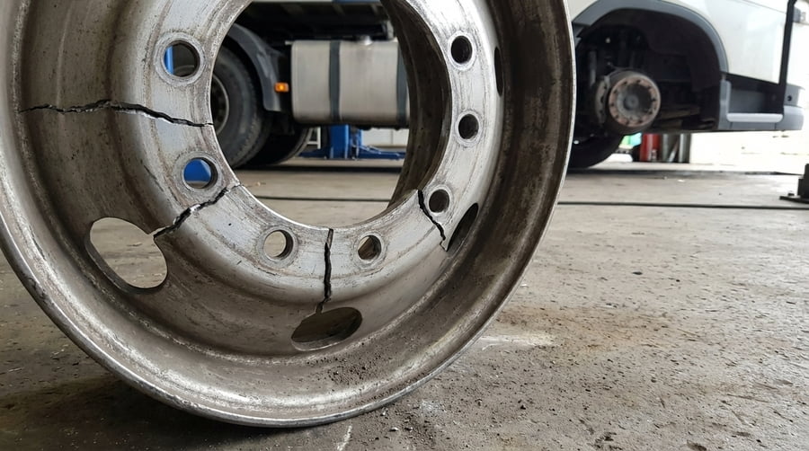
You are facing a wheel failure and trying to find the cause. You suspect a bad batch of steel or poor-quality welds5, which are common culprits in manufacturing defects.
An incorrect offset is almost always more dangerous and will cause a failure faster than typical material defects. While poor material might reduce fatigue life10, an incorrect offset actively multiplies the forces the OTR wheel experiences, accelerating fatigue at an exponential rate.
This is a hard lesson I've seen many operations learn. A material defect, like a small inclusion in the steel or a slightly imperfect weld, creates a weak point. It might reduce the OTR wheel's fatigue life10 by 20% or 30%. But an incorrect offset changes the entire dynamic of the system. It's not just making the wheel weaker; it's actively hitting it harder with every single rotation. This amplified force can reduce the fatigue life10 by 90% or more. A perfectly manufactured wheel made from the best steel in the world will fail quickly if the offset is wrong. Conversely, an average-quality wheel with the correct offset will almost always outperform a premium OTR wheel with the wrong offset. Getting the geometry right is the most critical factor for wheel longevity. Before you blame the steel, always check the offset.
How Do You Ensure You Have the Correct OTR Wheel Offset?
Knowing the danger of incorrect offset, how can you be certain that the wheels you are buying and installing are geometrically perfect for your machines to avoid these failures?
You must move beyond basic specs like diameter and bolt pattern. The wheel's part number or, even better, a detailed technical drawing11, is the only reliable way. Partner with a supplier who understands this and can verify or even custom-design12 a wheel to match your machine's exact requirements.
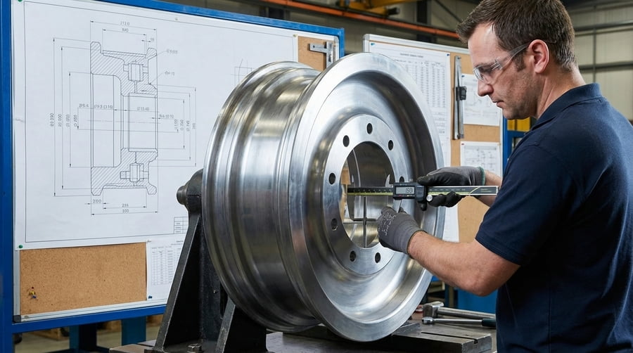
Over my 12+ years in this business, I've learned that assumptions are expensive. Never assume a wheel that looks the same will work the same. The first step is always to confirm the machine's required offset from the original manufacturer's specifications. The second step is to demand that your supplier provides a wheel that matches this spec exactly. At Gescomaxy, this is a core part of our process. We don't just sell a "25-inch rim." We provide a solution based on a technical drawing11 that specifies the offset down to the millimeter. For clients with unique needs or older machines where specs are lost, we can reverse-engineer the requirement from an existing OTR wheel or design a custom solution. This focus on geometric accuracy13, especially offset, is the key to preventing fatigue failures14 and ensuring long-term reliability.
Conclusion
Offset is not a detail; it's a critical safety and performance parameter. The right offset ensures reliability, while the wrong offset guarantees failure, no matter the wheel's quality.
Gain insights into how load ratings are calculated and their importance for safety. ↩
Understanding OTR Wheel offset is crucial for ensuring vehicle safety and performance. ↩
Learn about the lever arm concept and its significance in mechanical engineering. ↩
Explore how bending stress influences wheel durability and safety in heavy machinery. ↩
Explore different welding techniques and their importance in wheel construction. ↩
Learn about the factors contributing to metal fatigue and how to prevent it. ↩
Discover maintenance tips to enhance the performance and longevity of articulated dump trucks. ↩
Understand the concept of safety margins and their role in engineering safety. ↩
Understand the concept of eccentric bending forces and their impact on wheel integrity. ↩
Find strategies to enhance the fatigue life of mechanical components, including wheels. ↩
Discover how technical drawings ensure precision and accuracy in engineering projects. ↩
Explore the benefits of custom-design solutions for optimizing equipment performance. ↩
Learn why maintaining geometric accuracy is essential for product reliability. ↩
Explore the causes of fatigue failures and how to prevent them in wheel applications. ↩