You need to adjust your machine's track width, so you consider changing the wheel offset. A few millimeters seems like a minor, harmless tweak to get the clearance you need.
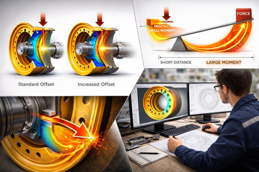
Increasing OTR wheel offset1 doesn't just add stress; it multiplies it exponentially. A small change in offset acts as a longer lever, creating a disproportionately massive increase in the bending moment2 on the OTR wheel disc3, which can slash the wheel's fatigue life4 and lead to premature failure.
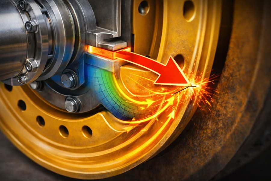
I once had a client, a fleet manager for a large quarry, who was retrofitting new tires onto his loaders. To get the necessary clearance from the struts, his local mechanic suggested using wheels with just a 20mm greater offset. It seemed like an easy fix. Six months later, he called me, frustrated. He had a loader down because the OTR wheel disc3 had cracked right around the bolt circle. He blamed the quality of the wheel, but the real culprit was that "minor" 20mm change. He fell into a common trap: assuming the effects of offset are small and linear. Today, I want to explain the dangerous physics behind that assumption.
Why Can't You Assume Twice the Offset Equals Twice the Stress?
It’s logical to think that if you increase the offset by 10%, you increase the stress by 10%. This kind of linear thinking makes sense, but in wheel engineering, it’s a dangerous mistake.
Because offset acts as a lever arm5, the relationship between offset and stress isn't linear; it's exponential. Doubling the offset doubles the bending moment2, but this new load can quadruple the stress on critical areas6, causing fatigue to accumulate much faster.
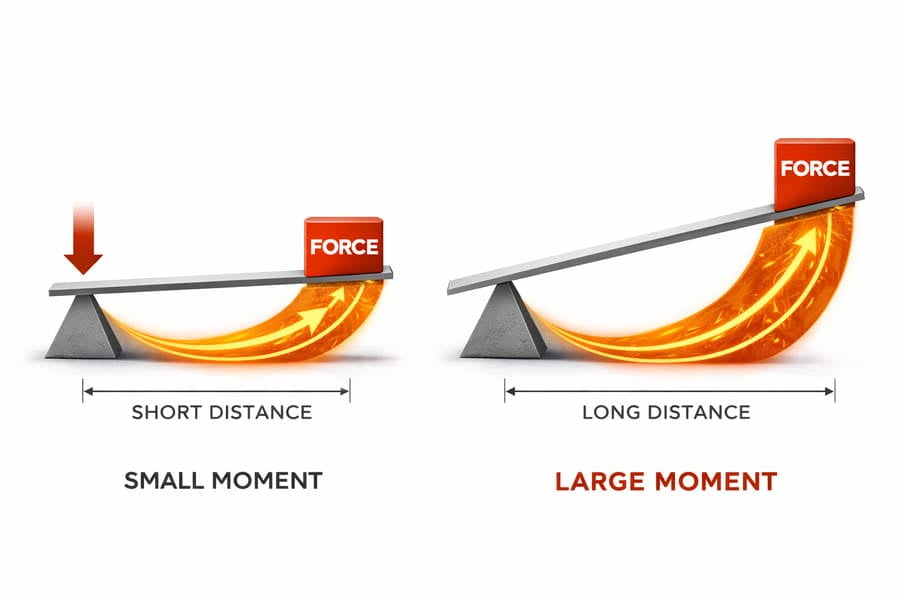
The key here is understanding the concept of a bending moment2. Think about using a wrench to tighten a bolt. A short wrench requires a lot of effort. A long wrench makes it easy. The offset on a wheel is like the length of that wrench. The machine's weight is the force you apply. The bending moment2 is the twisting force the wheel disc3 experiences, and it's calculated as Force x Distance (Offset). So yes, doubling the offset doubles the bending moment2. However, the way steel fatigues under stress is not a simple 1-to-1 relationship. The increased stress gets concentrated in the wheel's structure, especially around welds and bolt holes. This concentration means that a doubled bending moment2 can lead to a much more significant increase in localized stress, causing the material to fail exponentially faster. It's a classic case where the engineering reality7 defies simple arithmetic.
How Can a Few Millimeters of Offset Cause a Massive Failure?
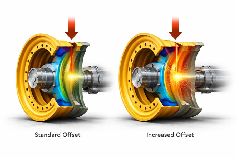
You look at a massive OTR wheel and find it hard to believe that a change you can barely see—10 or 20 millimeters—could possibly lead to a catastrophic crack on a thick steel disc.
Those few millimeters extend the lever arm5, and even a tiny extension creates a significant percentage increase in the bending moment2. On a wheel already designed to its optimal safety margin8, this extra load is enough to push stress beyond its fatigue limit.
Let's use some real numbers. Imagine a large wheel with a standard offset of 150mm. This is the "lever arm5" the wheel was designed for. Now, let's add just 20mm to get more clearance, making the new offset 170mm. That's only a 13% increase in offset. It seems tiny. But this 13% increase in the lever arm5 results in a 13% increase in the total bending moment2 applied to the OTR wheel disc3 with every single rotation. A high-quality OTR wheel is engineered to handle a specific load for millions of cycles with a precise safety factor. This "small" 13% extra load can be the straw that breaks the camel's back. It eats into that safety factor and dramatically accelerates metal fatigue9. The original design might have been rated for 20,000 hours, but with the new, higher stress, it might now fail in just 5,000 hours. The change was small, but the consequence was huge.
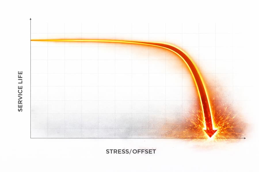
How Does Increased Offset Make Service Life Collapse So Rapidly?
You might expect a wheel with a slightly higher offset to wear out a little faster. But you're not seeing a gradual decline; you're seeing wheels that look fine one day and are cracked the next.
Fatigue life is exponentially related to stress. Once stress exceeds a certain threshold, the number of cycles a wheel can endure before cracking drops off a cliff. A small increase in continuous stress doesn't shorten the life; it collapses it.
This is one of the most counter-intuitive parts of metal fatigue9. Imagine a paperclip. You can bend it back and forth slightly a hundred times, and nothing happens. But if you bend it just a little bit further each time, it doesn't last 80 times; it might snap after only 10 bends. Steel behaves in a similar way. Every OTR wheel is designed to handle a certain stress level for a target number of cycles (its fatigue life4). As long as the stress stays below that critical design limit, the OTR wheel can last for its intended lifespan. The moment you increase the offset, you increase the stress with every rotation. This new, higher stress level might be on a completely different part of the fatigue curve.
The Fatigue Curve Cliff
| Stress Level | Expected Fatigue Life (Cycles) |
|---|---|
| Designed Stress | 2,000,000 (Very Long Life) |
| Designed Stress +10% | 1,000,000 (Life Halved) |
| Designed Stress +20% | 250,000 (Life Collapses) |
As you can see from this illustrative table, a small, linear increase in stress leads to an exponential, catastrophic drop in service life. This is why a OTR wheel doesn't just "wear out faster"; it fails suddenly and prematurely.
Why is Custom Engineering a Safer Solution Than Standard Offsets?
Given the risks, you might wonder how to safely get the clearance you need. Is it better to find a standard OTR wheel that's "close enough" or to pursue a different path?
A custom-engineered solution10 is always safer because it redesigns the OTR wheel's structure to handle the new offset. Instead of just adding leverage, it redistributes mass and strengthens critical areas6 to create a new, balanced design with the original safety margin8s intact.
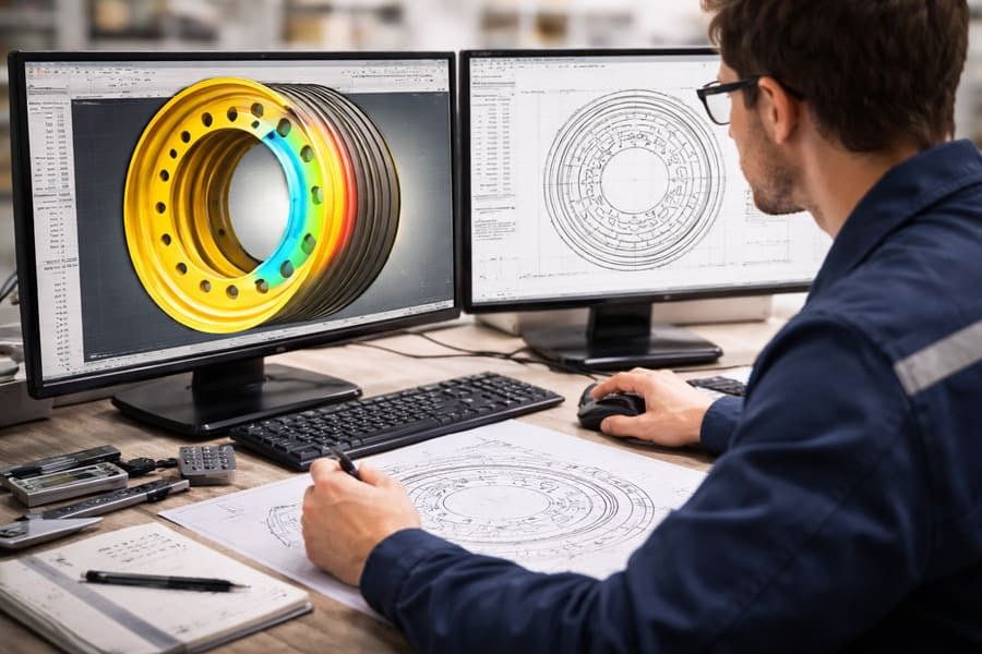
When a client comes to us at Gescomaxy needing a non-standard offset, we don't just shift the mounting surface. We start a new engineering process. Our team uses Finite Element Analysis (FEA)11 to model the new bending moment2 created by the required offset. Then, we redesign the OTR wheel disc3 itself. This might mean increasing the thickness of the disc, changing the shape of the profile to better distribute stress, or reinforcing the areas around the bolt holes and welds. We are fundamentally re-balancing the design to handle the new geometry. The goal is to create a wheel that, despite its different offset, has the same fatigue life4 and safety factor as the original standard OTR wheel. This is the difference between a simple modification and a true engineering solution12. It ensures you get the fit you need without unknowingly compromising the safety and reliability of your equipment.
Conclusion
Increasing OTR wheel offset1 is a dangerous game of leverage. The relationship between offset and stress is exponential, meaning small changes can cause a catastrophic collapse in the wheel's service life.
Understanding OTR wheel offset is crucial for optimizing performance and safety in heavy machinery. ↩
Learn about bending moments to grasp how they impact the structural integrity of wheels and other components. ↩
Learn about wheel disc design to enhance performance and durability in heavy machinery. ↩
Explore fatigue life calculations to understand how stress affects the longevity of mechanical components. ↩
Understanding lever arms can help you comprehend the mechanics behind wheel offset and stress. ↩
Identifying critical areas can help you focus on strengthening designs for better performance. ↩
Explore the gap between theory and practice in engineering to improve your designs. ↩
Learn about safety margins to ensure your designs meet necessary safety standards. ↩
Learn about metal fatigue to understand how small changes can lead to significant failures. ↩
Explore the advantages of custom engineering to ensure safety and reliability in machinery. ↩
FEA is a powerful tool in engineering; understanding it can enhance your design processes. ↩
Learn what makes an effective engineering solution to ensure reliability and safety. ↩