Your brand new OTR wheel passes every strength test and exceeds its load rating. Yet, months later, a crack appears during a routine operation. You're left wondering what went wrong.
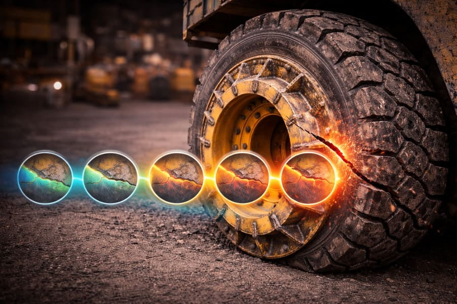
Most OTR wheel failures1 are not caused by a single, massive overload but by metal fatigue2. This is a gradual weakening of the steel from millions of repeated cycles of loading and unloading—like rolling, turning, and hitting bumps—which eventually causes a crack to form and grow over time.
I once had a client who operated a large fleet of port machinery. He only ever asked about one number: the maximum static load capacity3. He thought a higher number meant a better wheel, period. We supplied wheels that far exceeded his load requirements, but he still saw failures. It took a while to explain that the problem wasn't the wheel's ability to hold the weight of the machine. The problem was the thousands of stop-start cycles, sharp turns, and container loading impacts his machines went through every single day. He was thinking about strength; his wheels were failing from fatigue.
Is a "Strong" OTR Wheel the Same as a "Durable" Wheel?
You buy a OTR wheel based on its high static load rating, thinking it’s indestructible. Yet, it fails much sooner than expected in a standard application, leaving you frustrated and questioning the quality.
No, a "strong" OTR wheel is not the same as a "durable" one. A strong OTR wheel resists a single, extreme event. A durable, fatigue-resistant wheel4 survives millions of repeated, smaller stresses. Field failures are almost always a durability issue, not a strength issue.
Think of it like this: strength is like a weightlifter who can lift 500 pounds one time. It's an incredible display of peak power. Fatigue life, on the other hand, is like a marathon runner who can run for 26 miles, step after step after step. You would never judge the weightlifter's ability to run a marathon based on his one-rep max lift. They are completely different abilities. In OTR wheels, "strength" ensures the wheel won't collapse if you drop the machine from a small height. "Fatigue life" ensures the OTR wheel can complete millions of rotations over thousands of hours without cracking. We design for the marathon, not just the single heavy lift.
Strength vs. Fatigue: Two Different Jobs
Understanding this difference is key to wheel reliability.
| Feature | Strength (Static Load) | Fatigue Life (Dynamic Load) |
|---|---|---|
| What it Measures | Ability to survive a one-time peak load. | Ability to survive millions of repeated loads5. |
| The Test | "Can it lift 500 lbs once?" | "Can it lift 100 lbs a million times?" |
| Real-World Event | Hitting a huge boulder, a hard landing. | Normal rolling, turning, braking, and bumps. |
| Failure Mode | Bending, deforming, or fracturing instantly. | A small crack forms and grows slowly over time. |
Why Do OTR Wheels Break Under Normal Conditions?
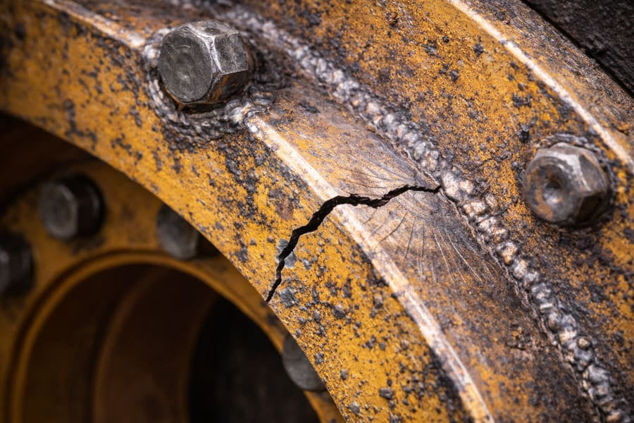
You inspect a failed wheel and see no evidence of a major impact. The machine was operating well within its load limits. So why is there a massive crack in the disc?
Wheels fail under normal conditions because damage from cyclic loading is cumulative. Each rotation, turn, and bump adds a tiny, invisible amount of stress. While no single cycle is dangerous, millions of them together "use up" the material's fatigue life6, eventually leading to a crack.
This concept is similar to bending a paperclip. You can bend it once, and it's fine. You bend it back, and it's still okay. But if you keep bending it back and forth in the same spot, even with very little force, you know what happens. It will suddenly snap. The paperclip didn't break because one of your bends was too forceful; it broke because of the repetition. The steel in an OTR wheel behaves the same way. Every time the wheel turns, the bottom of the disc is compressed and the top is stretched. This back-and-forth stress is the "bending" that slowly fatigues the metal. It doesn't fail at its peak load limit; it fails from the endless repetition far below that limit.
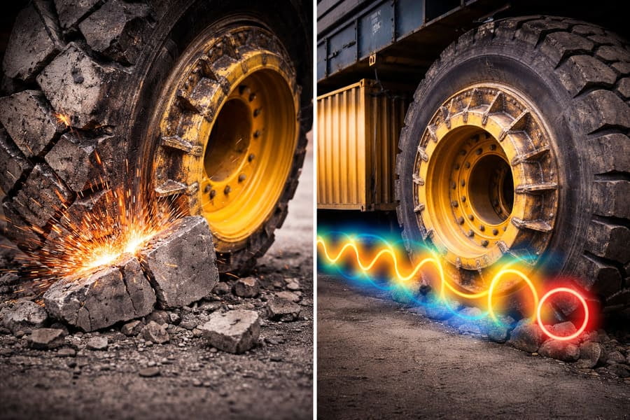
The Real Enemy: Cyclic Loading
The true test of a wheel isn't a single event, but its entire service life.
- Rolling: Every rotation flexes the wheel disc.
- Braking & Accelerating: This transfers torque, creating stress between the disc and rim.
- Turning: Side forces put enormous strain on the connection between the hub and the wheel disc.
- Impacts: Even small bumps on uneven ground send stress waves through the entire structure.
Each of these is a "cycle" that eats away at the wheel's life.
How Can a Design Be Both Strong and Fatigue-Resistant?
You're told a wheel is "over-engineered" for strength, which sounds good. But if strength alone isn't enough, how do engineers build a wheel that can also handle a lifetime of fatigue?
A great design manages stress, it doesn't just resist it. This is achieved not by adding more steel, but by using smarter geometry. Smooth transitions, rounded corners, and clean weld lines create a smooth path for stress to flow, preventing it from concentrating in one spot and starting a fatigue crack.
In my experience, the most common fatigue failures happen at sharp corners7 or weld transitions. Think of stress like water flowing through a pipe system. A sharp 90-degree corner causes turbulence and high pressure. A smooth, curved corner lets the water flow easily. In a OTR wheel, that "high pressure" is a stress concentration8. A good designer spends hours using computer simulations to find every one of these sharp corners7 and smooth them out. It’s also why we obsess over weld quality. A rough, uneven weld is like a series of small, sharp notches—perfect places for a fatigue crack to start. A smooth, clean weld allows stress to flow across the joint without interruption. It’s about creating a structure with no weak points for fatigue to attack.
Key Design Principles for Fatigue Life
- Smooth Geometry: Eliminate sharp corners7 and abrupt changes in thickness.
- High-Quality Welds: Ensure welds are smooth and fully penetrate to avoid creating built-in stress points.
- Clean Steel: Use high-quality steel with no internal impurities that could become a starting point for a crack.
- Correct Material Properties: The steel must have the right balance of strength and ductility (flexibility) to absorb energy without cracking.
Conclusion
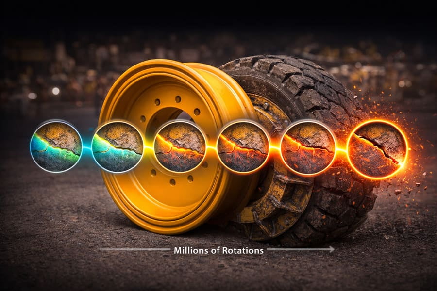
The real cause of most OTR wheel failures1 is fatigue from millions of cycles, not a lack of strength. A reliable wheel is one designed for the marathon of daily work.
Understanding the causes of OTR wheel failures can help you prevent future issues and improve wheel design. ↩
Learn about metal fatigue to better understand how it impacts the longevity and reliability of OTR wheels. ↩
Discover how load capacity is calculated to ensure you choose the right wheels for your machinery. ↩
Explore the characteristics of fatigue-resistant wheels to enhance your equipment's performance. ↩
Discover the effects of repeated loads on wheel lifespan to make informed decisions for your fleet. ↩
Explore the concept of fatigue life to better understand the longevity of your wheels. ↩
Learn why avoiding sharp corners in design is essential for enhancing wheel durability. ↩
Understanding stress concentration can help you appreciate the importance of design in preventing wheel failures. ↩