Your OTR rims are cracking in the same spot, again and again. You blame the material or the operator, but the real culprit is hidden in plain sight, dictated by the rim's own design.
The OTR rim's geometry1—its discs, gutters, and welds—creates specific pathways for force. Stress concentrates along these stiff routes instead of spreading evenly. Cracks appear at the weakest points along these predictable, high-stress paths, not randomly.
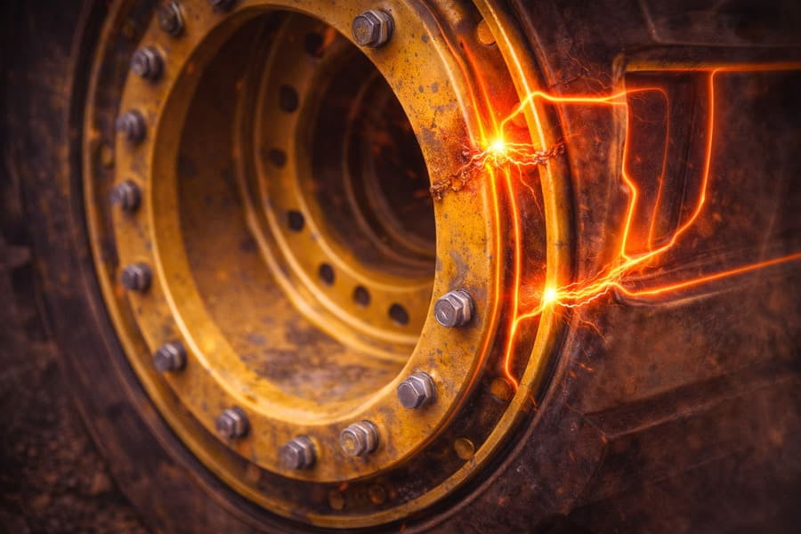
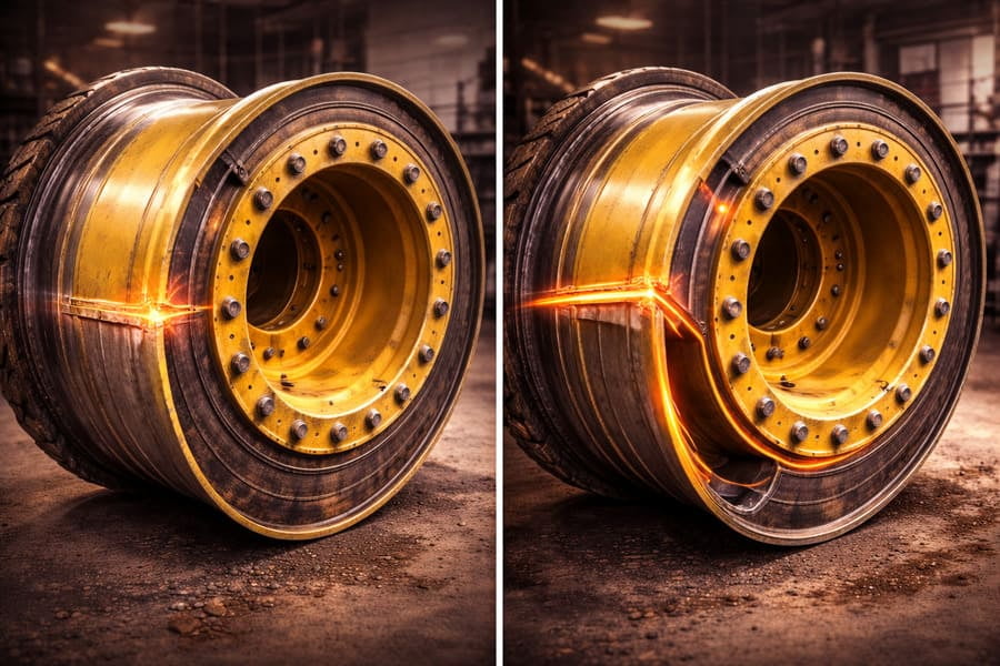
I've seen this countless times. A client sends me a photo of a crack in a five-piece OTR rim2, usually near the bead seat band weld3 or at the disc connection. Before I even open the file, I have a good idea of where it will be. This isn't magic; it's physics. Force behaves in predictable ways. To really understand why this happens, you have to stop thinking of a rim as a solid chunk of steel and start seeing it as a system of roads and bridges for stress. Where the cracks appear simply tells you which road is getting the most traffic and is overdue for repair.
You assume a massive, solid steel rim distributes force uniformly, like water filling a bucket. Yet, failures always seem to happen in very specific, localized spots.
A OTR rim is not a uniform block; it's a complex assembly of different shapes and thicknesses. Force always follows the path of least resistance, which in steel means the stiffest route. This naturally concentrates stress instead of spreading it.

Think of a crowd exiting a stadium4. People don't spread out evenly across the open field. They naturally funnel toward the clearly marked, paved exit gates. Force does the same thing inside a OTR rim. The thick, welded areas and the sharp corners of the disc are like the "paved gates"—they are much stiffer than the flatter, more flexible parts of the rim. So, all the load from the machine wants to travel through these stiff sections. The stress doesn't share itself nicely; it gets crowded into a few specific areas. This is why a crack can form next to a perfectly good section of steel—the load was never shared between them in the first place. The design itself created a traffic jam of stress.
How Does the OTR Rim's Shape Define the Path of Force?
You see a complex structure of discs, gutters, and flanges. You know it holds the tire, but how does that shape actually control the immense forces at play?
The OTR rim’s geometry and weld locations act like a roadmap for stress. The connection points between the disc and the OTR rim base are the critical intersections where forces from braking, driving, and cornering must be transferred.
Every part of the rim's structure has a job. The disc, for example, is the bridge that transfers torque from the axle to the tire. The path this force takes is determined entirely by the shape and position of the disc and its welds.
Force's Journey Through a Rim
| Force Type | Rim Component | Path of Force | Common Stress Point |
|---|---|---|---|
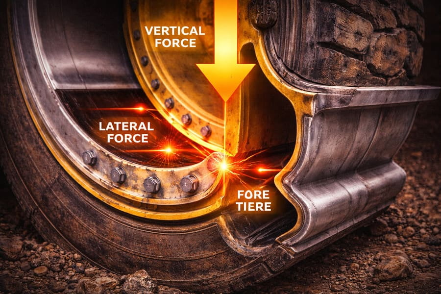
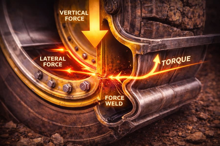
| Vertical Load (Weight) | Disc & Rim Base | From tire, through bead seat, into the rim base, supported by the disc. | Weld between disc and base. |
| Driving/Braking Torque | Disc & Mounting Ring | From axle, through the bolt holes, across the disc, to the rim base. | Bolt hole area and disc welds. |
| Lateral Force (Cornering) | Flanges, Disc, Gutters | Pushes sideways on the tire/flange, transferring stress through the disc. | Gutter section and disc welds. |
As you can see, the weld joining the disc5 to the rim base is a major intersection for all types of forces. It's the busiest intersection in the city. This is why a huge portion of rim fatigue cracks start right there. The structure literally forces stress to concentrate at that point.
Why Is a Crack a Map of Past Stress?
A crack appears on your OTR rim, and your first reaction is to get it repaired. But what if that crack is telling you a valuable story about your operation?
A crack is the physical evidence of a failed load path. Its location, size, and direction are a perfect map that reveals exactly how and where stress has been accumulating in the rim over its service life.
As a manufacturer, cracks are one of the most valuable sources of data we can get. They are the OTR rim's final report card. When a customer sends me a failed rim, I don't just see damage; I see data. A crack at the base of the bead seat band tells me the tire was likely running underinflated, causing the rim to flex excessively. Cracks radiating from the bolt holes point to improper torque on the nuts or an uneven mounting surface. A crack in the gutter section on a loader rim often points to high lateral forces from sharp, aggressive turning. By reading the map left by the crack, we can work backward to diagnose the root operational issue6. The crack isn't just the problem; it's also the key to the solution.
How Can This Knowledge Prevent Future OTR Rim Failures?
Understanding load paths is interesting, but how does it actually help you, the person responsible for keeping machines running and managing costs?
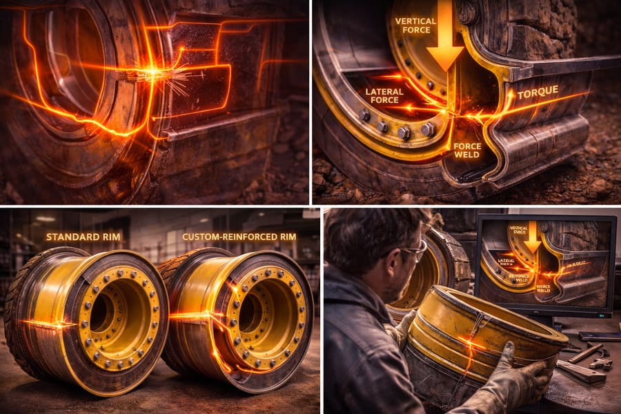
By understanding that structure dictates stress, you can partner with your supplier to select or design a rim with reinforcements exactly where your specific operation needs them7 most, preventing predictable failures8.
Once you know why OTR rims crack, you can stop reacting to failures and start preventing them. If your loaders are constantly making sharp turns, you know the gutter section and disc welds are taking a beating. You can then work with a manufacturer like us to source a rim with a thicker gutter or a reinforced disc weld profile. If your problem is heavy loads and rough ground, you need a stronger connection between the disc and the base. This moves the conversation beyond a simple spec sheet. It becomes a collaboration. You bring your knowledge of the operating conditions, and we bring our knowledge of how to design a structure to handle them. This proactive approach, based on understanding load paths, is the most effective way to reduce downtime and lower your total cost of ownership9.
Conclusion
A OTR rim crack is never random. It is the predictable result of stress concentrating along paths defined by the OTR rim's structure. Understanding this helps you diagnose issues and prevent future failures.
Explore how the geometry of OTR rims affects stress distribution and crack formation. ↩
Discover the benefits and challenges of using five-piece OTR rims in heavy machinery. ↩
Understand the critical function of bead seat band welds in maintaining rim strength. ↩
Explore this analogy to better understand how forces behave in physical structures. ↩
Learn about the significance of welds in load-bearing structures and their failure points. ↩
Understand the diagnostic value of cracks in identifying underlying operational problems. ↩
Discover how tailored reinforcements can enhance rim performance based on operational demands. ↩
Learn proactive measures to avoid common rim failures and improve operational efficiency. ↩
Explore how understanding TCO can lead to better decision-making in equipment management. ↩