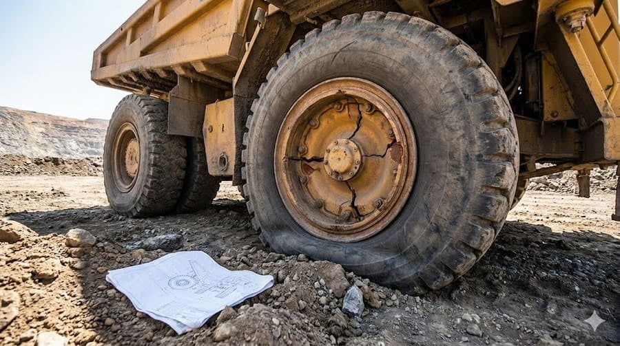
You’ve installed a new OTR wheel1, triple-checking that every dimension—diameter, width, bolt pattern—is a perfect match. Yet, months later, it fails. The frustration is immense; you followed the book.
A wheel with the "correct size" fails because static dimensions don't guarantee dynamic performance2. Premature failure is often caused by incorrect wheel offset3 creating excessive leverage, or a design that doesn't match the machine's true load path4, leading to concentrated stress and fatigue.
After more than a decade in the OTR wheel1 business, I've seen this scenario play out too many times. A client calls, completely baffled. They believe they received a defective product, but the real issue is far more subtle. The industry's focus on "fitment" often overlooks the brutal physics of a machine in motion. A wheel isn't just a static part; it's a dynamic component that must manage immense and complex forces. Let’s break down why a wheel that fits perfectly can still be the wrong wheel for the job.
Why Does My Spec-Perfect OTR Wheel Behave Like It's the Wrong Size?
You've matched the specs perfectly, but you're seeing uneven tire wear5 or, worse, stress marks6 around the hub. It feels like the wheel is somehow misaligned, even though it isn't.
This happens because the wheel's nominal size doesn't reflect its dynamic load radius7. Under load, forces aren't applied where specs suggest, causing eccentric loading8 and unexpected stress on the wheel and machine.
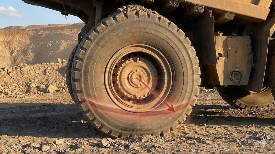
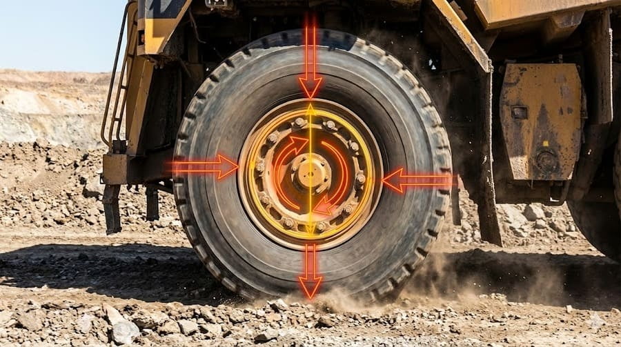
Think of it this way: the technical drawing shows a perfect circle. But when a 50-ton loader puts its weight on that wheel and tire assembly, the tire flattens. The actual center of pressure shifts. Standard certifications, like ISO, are brilliant for confirming a wheel will physically bolt onto a hub. They check for geometric compatibility. However, they don't simulate how that wheel will behave under the specific load and torque of your machine. This mismatch between the static blueprint and the dynamic reality is where problems begin. The load isn't centered as designed, leading to wobbling, vibration, and stresses that the wheel was never intended to handle.
Beyond the Blueprint: Static vs. Dynamic Reality
A spec sheet tells part of the story, but the machine's operation tells the rest. Understanding the difference is key to reliability.
| Parameter | Static Measurement (The Spec Sheet) | Dynamic Reality (The Real World) |
|---|---|---|
| Load Point | Assumed to be at the geometric center of the wheel. | Shifts based on tire deflection, torque, and side forces. |
| Focus | Geometric fitment—will it bolt on? | Load behavior—how will it perform under stress? |
| Standard Check | Verifies dimensions and bolt pattern compatibility. | Often un-tested, leading to risk being passed to the user. |
| Result | A wheel that "fits." | A otr wheel that may wear unevenly and cause stress on bearings. |
How Can a Small Change in Wheel Offset Cause a Catastrophic Failure?
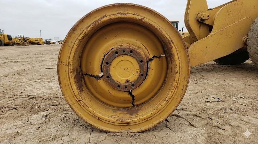
Your replacement wheel fits the hub and clears all components. But months later, it cracks near the mounting plate. You blame the steel quality, but the real culprit is hidden in plain sight.
Even a minor change in wheel offset3 dramatically alters the bending moment9 on the wheel disc and hub assembly. This leverage effect multiplies stress, accelerates metal fatigue10, and leads to premature cracks, even if the wheel's load rating seems adequate.
I always use this analogy: try holding a 10kg weight close to your chest. It's manageable. Now, hold that same weight with your arm fully extended. You feel immense strain in your shoulder. The weight didn't change, but the leverage did. Wheel offset works the exact same way. The offset determines how far the tire's centerline is from the mounting face of the wheel. If the offset is wrong, you're essentially moving the "weight" (the entire load of the machine) further out. This creates a massive leverage force, or bending moment9, that constantly tries to pry the wheel disc away from the hub. This is a load-path problem. The stress is no longer flowing where the designers intended, and the metal fatigue10s exponentially faster.
The Hidden Power of Leverage
Offset isn't just a clearance measurement; it's a critical structural parameter.
- What is Bending Moment? It's the rotational force that occurs when a force is applied at a distance from a pivot point. In a wheel, the pivot is the hub, and the distance is the offset.
- Exponential Stress: A small increase in offset doesn't just create a small increase in stress. The relationship is often exponential, leading to rapid fatigue.
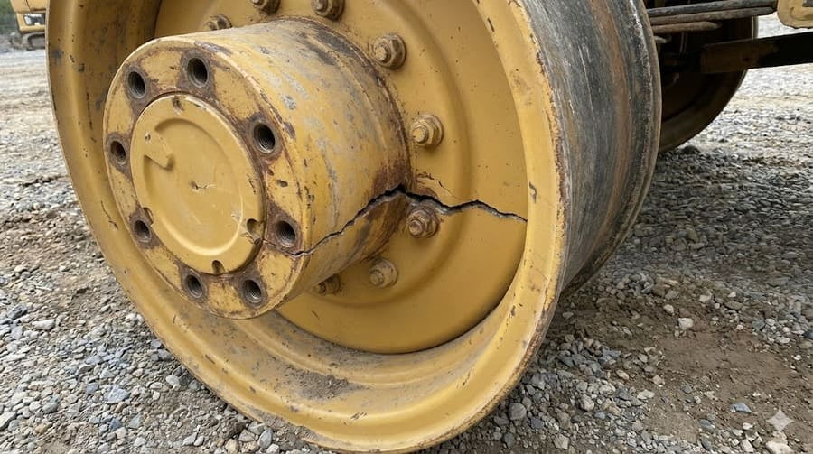
- The Failure Point: This excessive leverage is why cracks almost always appear around the mounting holes or the connection between the disc and the rim base. The wheel is literally being torn apart by physics.
If It Fits, Why Doesn't It Last?
You've ensured the size and offset are correct. The wheel is certified. Yet, failures persist. You start to think that all OTR wheel1s are simply built to fail, and it's just a cost of doing business.
A wheel that fits is not the same as a wheel engineered for the machine's specific load path4. Fitment ensures it can be bolted on; correct engineering ensures it can survive the unique dynamic forces of its real-world application.
This is the most critical point of all. The problem isn't a manufacturing defect; it's a design-to-application mismatch. The phrase "fits doesn't mean lasts" should be posted in every procurement office11. When a wheel fails, it's because the load path4—the journey that forces take from the ground, through the tire and wheel, and into the axle—was not respected. Did the original design account for the side-slope operation of a grader? The sharp, jarring impacts on a quarry dump truck? The constant torsional stress on a container handler? Most standard-size wheels do not. This is why we, as your supplier, must act as an engineering partner. We must ask about the machine, the terrain, and the duty cycle to ensure the wheel we provide doesn't just fit, but lasts.
Engineering for the Load Path
True reliability comes from moving beyond simple fitment to application-specific engineering.
| Fitment-Based Approach | Load-Path-Based Approach (Our Method) | |
|---|---|---|
| Question | "What are the dimensions?" | "What is the machine and how will it be used?" |
| Focus | Matching a spec sheet. | Analyzing dynamic forces and stress points. |
| Responsibility | Ends when the wheel is shipped. | Extends through the lifecycle of the wheel. |
| Outcome | Predictable failures, increased downtime. | Enhanced reliability, lower total cost of ownership. |
Conclusion
A "correct size" OTR wheel1 fails when its design ignores the dynamic load path4. True reliability comes from engineering for the application, not just matching static dimensions on a spec sheet.
Explore this resource to understand how to choose the right OTR wheel for your specific needs. ↩
Discover the differences between dynamic performance and static measurements in engineering. ↩
Learn about the critical role of wheel offset in ensuring optimal performance and longevity. ↩
Explore the concept of load path and its importance in wheel and machine design. ↩
Understand the factors leading to uneven tire wear and how to address them. ↩
Find out what stress marks can reveal about the condition of your wheels. ↩
Discover the significance of dynamic load radius in wheel performance and safety. ↩
Understand the concept of eccentric loading and its impact on wheel integrity. ↩
Gain a deeper understanding of bending moment and its relevance to wheel design. ↩
Learn to identify signs of metal fatigue to prevent wheel failures. ↩
Get insights into what procurement offices need to consider for wheel purchases. ↩